Distance
Sensing
devices
for wireless distance and position determination usefull as gesture controllers
for robotic musical instruments
by
dr.Godfried-Willem
Raes
post-doctoral
researcher
Ghent University College & Logos Foundation
2007/8
Since the early seventies we did build sonar devices to control
our self made analog electronic music synthesizers. In those years, simple to
use transducers were not readily available on the electronic component market
and so, we had to make our own, based on designs used for underwater hydrophones.
(Quarz crystals, inductive devices, self made condensor microphones etc...).
Although the focus of our research later on became doppler based sonar and radar
movement detection and gesture analysis, we always had quite a few pulsed sonar
devices at hand. The easiest and cheapest ones to build nowadays make use of
the commonly available 40kHz transducers. Two approaches are possible: either
one uses a single transducer as an emitter for a periodic burst of sinewaves
and that then is switched to microphone mode and connected to the input of a
voltage controlled amp (preferably a logamp, compensating for the square law
decay of amplitude with distance). The time between the start of the burst and
the reception of the first echo is a linear function of the straight distance
from the tranducer to the reflective object or body.
This design can be highly simplified as well as significanty improved in terms
of response time by using two separate transducers tuned to the same frequency,
one used as burst transmitter and the other one, placed in close proximity,
as receiver. Send - receive control can easily be confined to even the simplest
microprocessor. Even before the advent of microcontrollers, we did it using
nothing but discrete logic chips, a timer and some analog circuitry. Better
results than those obtained with these 40kHz piezo transducers can be achieved
using the popular Polaroid capacitive sensor, working on 50kHz. This sensor
however requires a very high polarising and high driving voltage (300V burst).
Because the diaphragm is pretty large (ca. 50mm), the sensor is very directional
and narrow beam.
The sampling rate, the shortest possible time between individual
distance measurements in all ultrasonic distance sensors is determined by the
velocity of sound (ca. 340m/s, although the velocity of sound in air decreases
for very high frequencies). This dictates that say for a measurement distance
of 3 meter, the time between measurements has to be much larger than 18ms. For
single transducer devices this time has to be increased with the required death
time between measurements required to discharge as well as damp sensors and
for resetting the operational conditions of the input circuitry. Thus the Polaroid
sensor is incapable to offer you more than ca 5 measurements a second. Although
all of these transducers give out distance data, it is technically very well
possible to gather also information on the size of the reflecting surface, since
this is proportional to the amplitude of the received echo. This parameter however
can only be reliably used if the reflective properties of the surface are not
subject to changes between measuments as is usually the case with clothed bodies.
This is one of the reasons why all our experiments, artistic presentations and
measurements are done using naked bodies. Another very obvious reason is that
clothing damps the amplitude of the reflected echo with a factor ranging between
-8dB to -18dB as compared to a naked body.
It will be clear that this ranging technology alone is not suitable
for acquiring information on gesture or even on pretty slow body movement. The
minimum required sampling rate to untertake this would be ca. 128 samples a
second, way above even what can be achieved with normal video cameras sampling
at 24 to 30 frames a second. (Raes, 1993). Trigonometric infrared distance sensors
(4) as well as radar sensors being the optimum choice for fast position and
gesture tracking.
However, slow distance measurement comes in handy as a complementary
information source in any doppler based radar or sonar system. For some 'popular'
instruments such as the Theremin, it is even mandatory. Nevertheless, for a
good theremin, response time has to be very fast indeed, dictating the use of
either radiofrequency or light based technologies.
Despite the inherent slowness of ultrasonic distance measurement,
we never stopped our investigations into these technologies. Doppler sonar and
radar systems lack the possibility of easy distance determination (7), and so,
a hybrid combination of sonar ranging with doppler radar seems very promising.
We do not combine pulsed sonar and doppler sonar, since this always leads to
mutual interference. Since a few years, a few long range proximity sensors became
available. One of these is the Pepperl+Fuchs UC6000-30GM-IUR2-V15, which we
used in an evaluation project in the context of our robotic M&M orchestra.
This distance sensor claims a measurement range between 350mm and 6000mm, for
a reflective surface of minimum 100mm x 100mm. It gives out an analogue voltage
between 0 and 10V linearly proportional to the distance. The operational range
can be programmed (limited) on the device itself. Temperature compensation is
part of the design of this transducer. The ultrasonic operational frequency
is ca.65kHz. The sampling rate, identical to the burst frequency is (our own
measument) 7.06 S/s. This sensor suffers from the same deficiency as just any
design in ultrasonic distance measurement we know off: it produces an audible
clicking noise synchronous with the burst frequency. Fortunately, the noise
level for this transducer is a lot lower than that for the Polaroid sensor.
If the sonic environment in which it gets used is loud enough and if it has
a reasonable amount of high frequency components in the spectrum, it will be
easily masked.
The distance resolution in itself is quite impressive with 0.35mm
over a range of 4000mm. This specification alone dictates the use of an ADC
with minimum resolution of 14 bits. Evidently, if one uses a setup consisting
of more than a single transducer, it becomes possible to acquire information
on the precise position of an object or body in a space. To this purpose, the
sensors are equiped with synchronisation and sequencing possibilities. This
of course at the detriment of sampling rate, since timing requires the transducers
to wait for each other. Only the cost of using an array of these Pepperl+Fuchs
transducers becomes prohibitive.
HY1
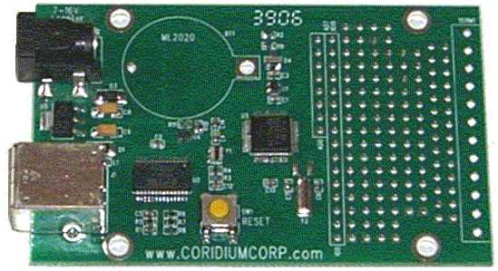
A first laboratory version of a hybrid sensor was developed using a 32 bit ARMmite
development board, programmable in Basic. It has a USB port for programming
and debugging. The ARM processor is an LPC2103 in a tiny LQFP-48 package clocked
at 60MHz. This system has 8 channels of on board ADC with a conversion speed
of 6µs. Resolution however is only 10 bits, as usual on nowadays microcontrollers.
The pins can be programmed for serial communication on the baudrate required
for MIDI (31250). However, since the board runs on 3.3V, some level shifters
are required to drive the midi output. To make the project a complete sensing
system for body movement we added one of our existing quadrada
radar frontend modules to the prototype design, such that we now can gather
information on distance, velocity of movement perpendicular to the axis as well
as body surface. Since the radar device is a two phase type (a Siemens KMY24,
operating on 2.4GHz) , we can also discriminate approaching and recessing movements.
By calculating the phase angles between the two amplitude channels and the two
tacho channels, we can derive information with regard to the aspect ratio of
the moving body as well as to the movement angle of the fast movements. The
data is send out as a midi stream of polyphonic key aftertouch messages. (160
+ channel, followed by two 7 bit data bytes: msb, lsb). The two data bytes -
seven bits each, as dictated by the midi standard, pack the information as follows:
the 3 low bits of the high nibble of the msb give the AD channel (0-4), the
low nibble of the msb gives the 3 most significant bits of the data, whereas
the LSB completes the data with the lowest 7 bits to a full 10 bit value.
The complete schematic for the hybrid one-dimensional transducer
unit is depicted below:
The midi channel used to transmit the data can be set with the
dip switches on the ARM board:
The ARMmite development board we used looks like:
When the distance sensor is able to return valid data, we return
a value for the size of the surface of the moving reflective surface independent
from the distance. This is calculated according to surface = (distance ^2) *
amplitude. Note that information for surface corresponds to the amplitude of
the signals received by the radar. If the distance is undeterminable by the
sensor, in which case it will output either zero or maximum, the value returned
for the surface will be uncertain and will reflect only the amplitudes as received
by both phases of the radar sensor alone. The radar-based movement velocity
values returned are independent from the distance. However, since the distance
sensor is one-dimensional, the value cannot be corrected for the angle of the
movement. (doppler frequency = speed * COS(angle) ) Thus, the movement velocity
value can only be relied on if taken between two valid values of distance, since
in that case we may assume a movement in axis with the line of sight of the
sensor. Note that there should always be a free line of sight (with no obstacles)
with an opening angle of 8 degrees in the range up to 6 meters from the sensor.
The angle and phase information can only in very specific cases, requiring information
on the gestures not retrievable with the sensor, be used to correct the speed
information. The polar diagram for the sensor combination clarifies this.
The tested and functional prototype firmware for the ARM 32-bit
processor written in ARM-Basic can be downloaded:
Arm_Midi_Daq_HY1.bas.
This firmware outputs each datachannel at a steady rate of 10S/s,
so the data burst frequency becomes 50 midi aftertouch messages a second. Oversampling
on the radar channels is applied internaly. The tacho channels are (over)sampled
at 40S/s and the surface channels at 20S/s. The data result of these channels
is an integrated value over the number of samples taken. The conversion of the
distance data (note that the distance sensor samples only at ca. 7S/s) to slow
movement axial speed expressed in m/s can be derived as:
v = 7 * (d(t0) - d(t2)) / 255.25
This of course only in the case that the databuffer contains
at least 3 valid values for the distance. Practical values fall within the range
-4.22m/s to + 4.55m/s. The sign of the value reflects the direction of the slow
movement: towards the sensor when positive and away from the sensor when negative.
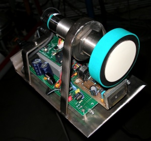
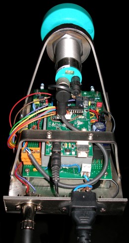
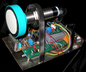
The prototype assembly of the hybrid sensor, baptized HY1, was
realized on a sturdy TIG welded stainless steel chassis, with a 3/8" thread
at the underside such that it can be mounted on a microphone stand. There are
just two connection wires: one for mains power and one for the midi output.
The large round component in top is the Pepperl+Fuchs transducer. Under it and
assembled in-line, we see the KMY24 Siemens radar sensor. The completed sensor
construction can be seen on the pictures following.
In the definitive circuit, we will use a PIC microcontroller
to convert the analogue signal from the Pepperl+Fuchs sensor to a stream of
UDP/IP messages via a network driver. This way, the sensor can be placed just
about anywhere a network connection is available and the data can be received
by any connected computer. The protocol we use is an adapted and extended form
of MIDI: device id, status byte, controller, data.
HY2
A second project on similar lines (baptised HY2), makes use
of a distance sensing device produced by Honeywell. The type number is 944-T4V-2D-1C1-130E.
The scan range is limited to 3.5m and the output is available as a 0-10V analog
voltage. The ultrasonic operational frequency is 130kHz and the beam angle 8
degrees. Response time -after the data sheet- is 120ms. We will report further
on this project as soon as completed.
The new devices are being developed by a team consisting of
myself, Johannes Taelman (PIC coding and development) and Kristof Lauwers (application
software layer).
Artistic applications
- Godfried-Willem Raes "Hybrid Sensing Study #1" (2007)
- Godfried-Willem Raes "De weg, Der Weg, The way" (2007), an act
in 'Technofaustus'
- Kristof Lauwers "Zy 1" (2007)
We are develloping a series of studies
and demonstrations to be performed by a naked performer, in which we try to
explore different ways of mapping the sensor information (alone or in combination
with either the sonar or radar version of our invisible instrument) on musical
activity produced by our robot orchestra, composed of following robots:
- <Player
Piano>, an automated piano
- <Harma>,
an automated harmonium
- <Piperola>,
automated treble pipe organ using flue pipes
- <Bourdonola>,
automated bass pipe organ using wooden pipes
- <Vox
Humanola>, automated pipe organ using vox humana reed pipes
- <Troms>,
an automated series of 7 drums with 24 beaters
- <Rotomoton>,
five automated rototoms
- <Flex>,
an automated set of singing saws
- <Thunderwood>,
automated percussion
- <Springers>,
automated large spring, shakers and siren
- <Dripper>,
automated rain machine
- <Vibi>,
automated vibraphone
- <Belly>,
an automated carillon made of shipbells
- <Klung>,
an automated brass angklung
- <Autosax>,
an automated saxophone
- <Tubi>,
an automated quartertone tubophone
- <So>,
an automated sousaphone
- <Puff>,
an automated percussive quartertone organ
- <Trump>,
automated low trumpet organ register
- <Hurdy>,
an automated hurdy gurdy.
- <Ake>,
an automated accordion.
- <Llor>,
an automated carillon made with stainless steel shells.
- <Sire>,
an automated assembly of 24 motor driven sirens.
- <Vacca>,
an automated collection of 48 cow bells
- <psch>,
an automated set of 12 small thundersheets
- <Krum>,
an automated organ register (Cromorno).
- <Snar>,
an automated snare drum
- <Vitello>, an automated
set of 36 cow bells
- <Bako>, an automated bass accordion
- <Qt>, an automated quartertone
pipe organ
- <Xy>, an automated quartertone
orchestral xylophone
- <Casta Uni> & <Casta Due>,
two robotic castanet players
- <Bono>, an automated valve
trombone
- <Heli>, an automated helicon
- <Simba>, an automated cymbal
player
- <Toypi>, a toy player piano
- <Ob>, an automated oboe
- <Aeio>, an automated cello
Everytime we finish a new robot and
add it to the M&M orchestra, we add a new chapter in this suite of pieces.
The sensor and signal conditioning circuit is available for any competent composer
wanting to develop a piece or performance using it. Since the use of the instruments
requires software to be written, it is highly advisible to study our <GMT>
software and its functionality with regard to this instrument. As an alternative,
the public domain language PD can be used as well. Usefull PD patches are being
developed by our collaborators Kristof Lauwers and Johannes Taelman. They will
be available upon demand. This device can be used in combination with our PicRadar
sensors operating on 9.5GHz as well as with a set of Quadrada
sensors operating on 2.4GHz.
Notes:
(1) This project is part of the ongoing research of the author
in gesture controlled devices over the last 30 years. Earlier systems, based
on Sonar, Radar, infrared pyrodetection and other technologies are fully described
in "Gesture controlled virtual musical
instrument" (1999), in "Quadrada"
(2003), "picradar" (2004) as well as in
his doctoral dissertation 'An Invisible Instrument' (1993). Artistic productions
and compositions using these interfaces and devices have been: <Standing
Waves>, <Holosound>, <A
Book of Moves>, <Virtual Jews Harp>, <Songbook>,
<Slow Sham
Rising>, <Gestrobo>, <Technofaustus>
, "PicRadar Studies" etc. The research is since 2005 supported in
part by the Ghent University College (Hogent).
(2) People interested
in buying the sensors as described here (fully functional and including the
programmed PIC or ARM processor) can take
contact with the author. Cost, depending on the version required start at
2200€ for a single transducer.
(3) Microcode for the PIC in the UDP/IP version of this project
is being written by Johannes Taelman.
(4) The Sharp infrared sensor (Type GP2Y0A02UYK)b with a range
of 20cm to 150cm samples distances only at a pace of 18.8Hz to 29.67Hz and would
be a bad choice here. It also has a lot of other deficiencies, such as very
high glitches on its analog outputs during data changes. We did apply it in
our bass-accordeon robot <Bako>,
and more details and experiences can be found on our webpage on that project.
(5) A short introductory note in dutch on this sensor project
in txt format can be downloaded. It was published
in the november issue of the magazine 'Logos Blad'.
(6) A slightly shortened version of this paper was presented
by the author at the occasion of the 'Pluck and Play for the muses' conference
held in Ghent, 1-5.07.2008.
(7) Distance determination using doppler radar devices is perfectly
well possible but has quite some complications: it requires the carrier frequency
to be frequency modulated. The phase difference between the modulation signal
and the reflected FM component becomes a measure for the distance to the reflecting
and moving object. In principle such an approach is also possible using doppler
sonar but one will meet problems with finding suitable transducers with a wide
enough bandwidth.
Bibliographical references:
- ANALOG DEVICES, AD736 datasheet (Linears), rev.H, Norwood 2007
- BECKMANN, Petr & SPIZZICHINO, Andre "The Scattering of Electromagnetic
Waves from Rough Surfaces", Pergamon Press, Oxford, 1963
- BHATIA, Avadh Behari "Ultrasonic Absorption", ed. Dover, London/NY
1985
- National Semiconductor Corporation, LM2907 datasheet (Linear databook, vol.3.
1988 edition), ISBN0-486-64917-2
RAES, Godfried-Willem "Een onzichtbaar muziekinstrument" (Gent,
1993)
- RAES, Godfried-Willem "Gesture controlled
virtual musical instrument" (Ghent, 1999)
- RAES, Godfried-Willem "Quadrada" (Ghent,
2003)
- RAES, Godfried-Willem "PicRadar" (Ghent,
2004-2005)
- SINCLAIR, Ian Rorbertson., "Sensors and Transducers" (London,
1992) , ISBN 0 7506 0415 8
First published on the web: 10.05.2007 by dr.Godfried-Willem
Raes
Last update:2010-03-13