|
Microtonal Musical Robot Research project on the development of new tools for musical expression at the University College Ghent
|
|
<Ob>
an oboe robot dr.Godfried-Willem RAES 2008-2010 |
|
Microtonal Musical Robot Research project on the development of new tools for musical expression at the University College Ghent
|
|
<Ob>
an oboe robot dr.Godfried-Willem RAES 2008-2010 |
<Ob>
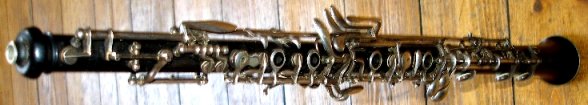
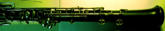
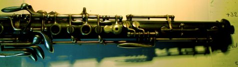
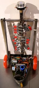
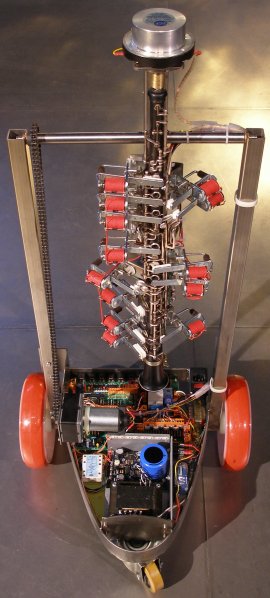
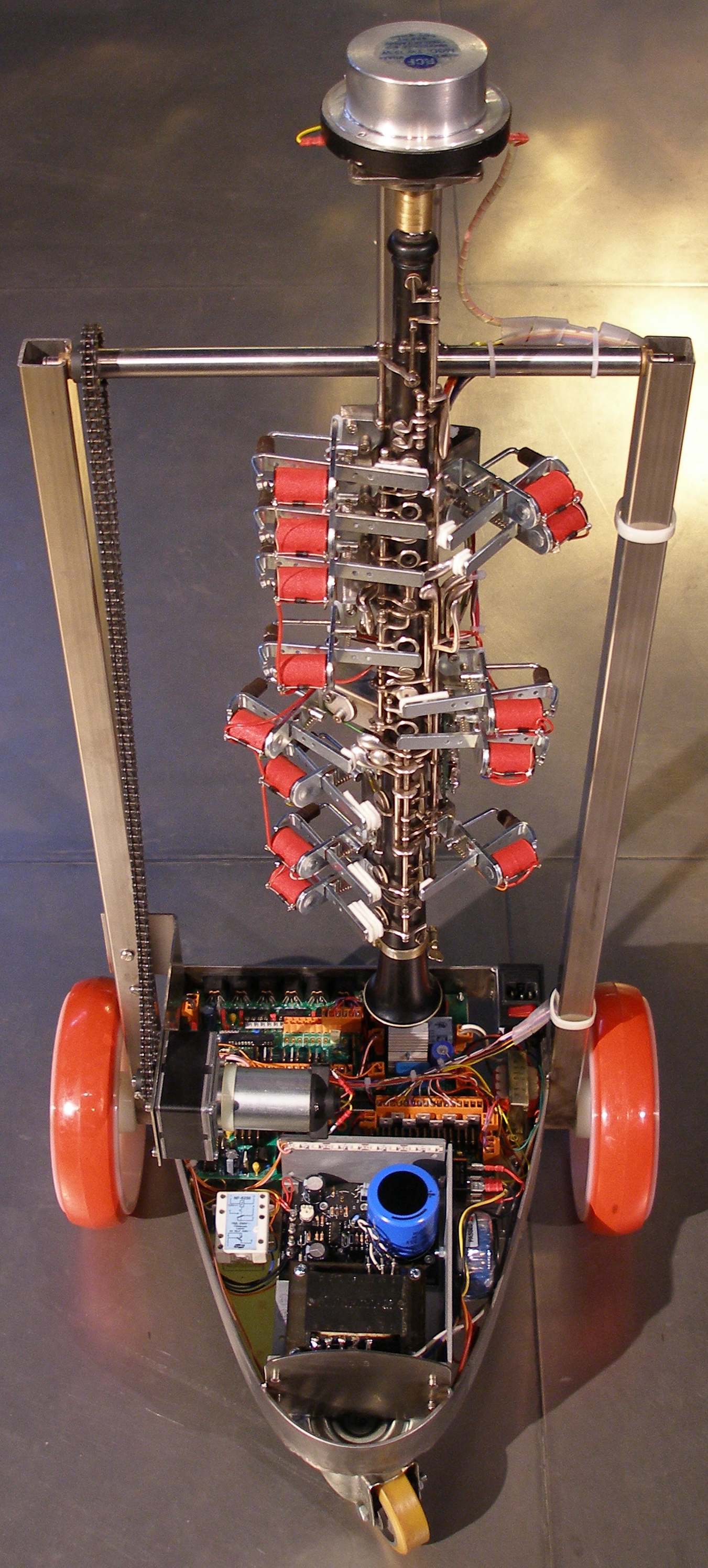
This musical robot belongs to the category of our automated classical music instruments: the oboe. The approach here was quite experimental and was an attempt to realistically automate an existing unmodified instrument, and thus it does in fact make use of a fine classical oboe. The instrument used is a Brussels made concert instrument by F.Debert, probably to be dated first half of the 20th century.
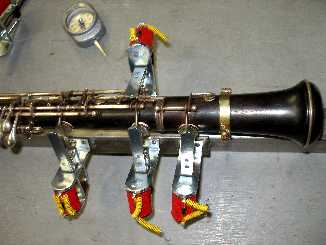
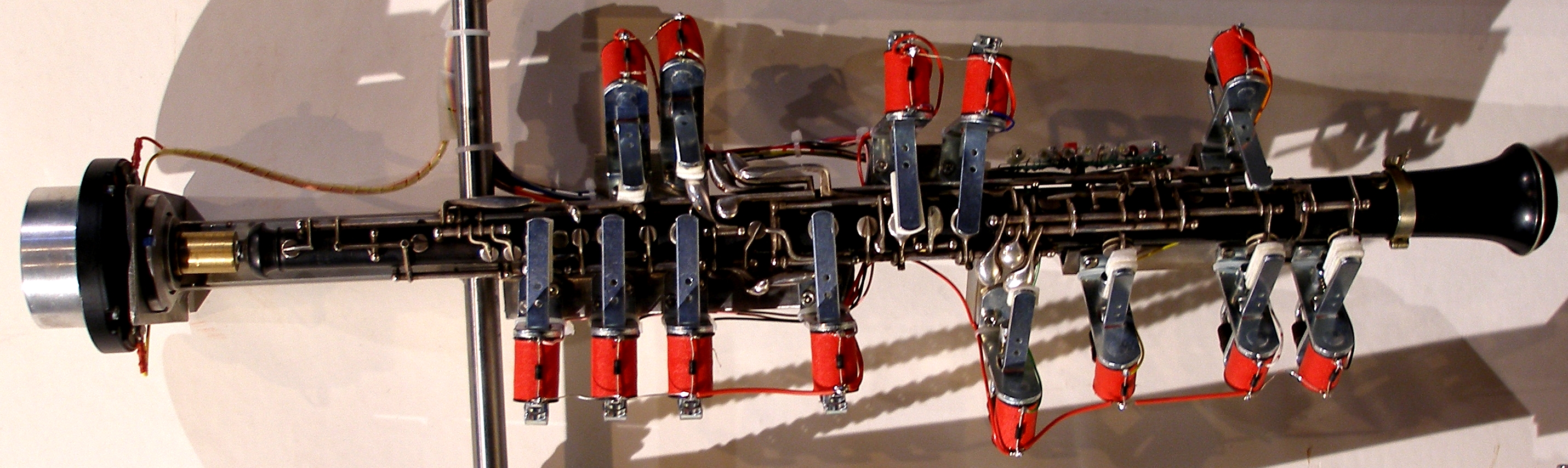
 Electromechanical control
of the levers did not confront us with any real problems apart from the quite
delicate and differentiated mechanics. Silent operation of these have been our
main concern. We simplified the fingerings such that we could suffice with less
than 16 solenoids: six closing the open holes, and the strict minimum of seven
for the essential levers. Some of the levers (such as the three octaving levers
as well as the levers to facilitate trills) are essential for players, but have
much less importance in an automated instrument where the attack of the tone
is guaranteed by the nature of the sound mechanism and where resonance on partials
can freely be used. Hence our simplified fingering table: the yellow lines indicate
the pads that are solenoid controlled in our final robot project.
Electromechanical control
of the levers did not confront us with any real problems apart from the quite
delicate and differentiated mechanics. Silent operation of these have been our
main concern. We simplified the fingerings such that we could suffice with less
than 16 solenoids: six closing the open holes, and the strict minimum of seven
for the essential levers. Some of the levers (such as the three octaving levers
as well as the levers to facilitate trills) are essential for players, but have
much less importance in an automated instrument where the attack of the tone
is guaranteed by the nature of the sound mechanism and where resonance on partials
can freely be used. Hence our simplified fingering table: the yellow lines indicate
the pads that are solenoid controlled in our final robot project.
On the left side of the table the notes/pitches are given as midi note numbers.
Levers that are in no instance colored red, were left un-automated in our robot.
For some levers, we did not implement a solenoid to action them the way human
fingers would do, but rather choose to automate the closing pad directly. We
are developing special fingering tables for quartertone and other microtonal
applications. Alternative fingerings in order to obtain different sound colors
are implemented as well. The standard fingerings are indicated as hexadecimal numbers in the right column
on the fingerchart.
The standard fingerings are indicated as hexadecimal numbers in the right column
on the fingerchart.
The double reed however, became the main problem. The first experiments conducted
us to the design and building of double reeds made from piezoelectric material
glued to brass plates. We got a few prototypes build along this line, up and
working and indeed the concept is workable. The main problem here was the very
low obtainable sound pressure, even when driving the piezo-material well above
its rated maximum voltage (35 V). The second series of experiments was carried
out using a double faced piece of piezoceramic bonded to a central brass plate
and placed just touching to an absolutely flat thick brass plate with a central
perforation of 4.2 mm. This mechanism gives a strong buzz but unfortunately,
sound production is very frequency dependent as well as dependent on applied
air pressure (after placing the assembly in a closed container). A secondary
problem in this approach was the noise generated by the compressor. We used
a small DC motor driven vacuum cleaner type compressor capable of producing
the required pressure of about 15 to 30 mBar. We dropped this prototype and
the compressor later was brought to good usage in our <Melauton>
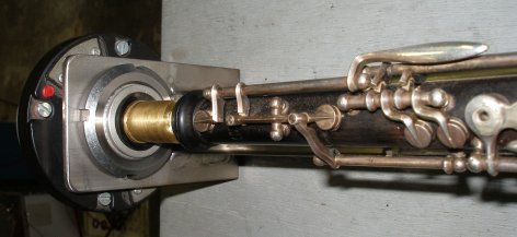
robot... Therefore a thirth series of experiments was carried out using tweeter
motor driver made for driving an exponential horn. Instead of coupling the driver
to an exponential horn, we designed an acoustic impedance converter modeled
after a real reed in a human mouth cavity. This piece had to be fabricated on
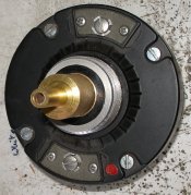
the lathe and is drawn here:  The 12 mm long cylindrical part on the left side of the piece fits inside the
outlet of the RCA pressure driver, without touching the titanium dome inside
however. The other side fits nicely into the oboe, replacing the reed. With
this mechanism, the realism of the produced sound becomes highly dependent on
the waveform applied to the driver. Something trapezoidal seems to work best.
However, in order to come close to original oboe sound, articulation is very
essential: frequency modulation, phase modulation of at least the first two
partials above the fundamental as well as some amplitude modulation (envelope
shaping).
The 12 mm long cylindrical part on the left side of the piece fits inside the
outlet of the RCA pressure driver, without touching the titanium dome inside
however. The other side fits nicely into the oboe, replacing the reed. With
this mechanism, the realism of the produced sound becomes highly dependent on
the waveform applied to the driver. Something trapezoidal seems to work best.
However, in order to come close to original oboe sound, articulation is very
essential: frequency modulation, phase modulation of at least the first two
partials above the fundamental as well as some amplitude modulation (envelope
shaping). 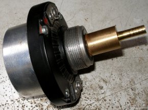 More
experiments with the exact shape of the acoustic impedance transformer will
be performed in the near future. The circuit for driving this motor was derived
from the circuits designed earlier for robots such as <Korn>, <Bono>
and <Aeio>:
More
experiments with the exact shape of the acoustic impedance transformer will
be performed in the near future. The circuit for driving this motor was derived
from the circuits designed earlier for robots such as <Korn>, <Bono>
and <Aeio>: It uses the same PC-board and the same 16-bit PIC microcontroller. The firmware
however, is quite different. For coupling of the circuit to the motor driver,
we use a classical audio output transformer. The two resistors and the capacitor
shown in the circuit diagram form a simple formant filter tuned together with
the inductance of the transformer, to the required strongest formant frequency
for oboe sound. Some experimentation with capacitor values was required here.
It uses the same PC-board and the same 16-bit PIC microcontroller. The firmware
however, is quite different. For coupling of the circuit to the motor driver,
we use a classical audio output transformer. The two resistors and the capacitor
shown in the circuit diagram form a simple formant filter tuned together with
the inductance of the transformer, to the required strongest formant frequency
for oboe sound. Some experimentation with capacitor values was required here.
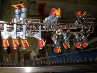
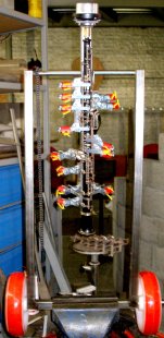
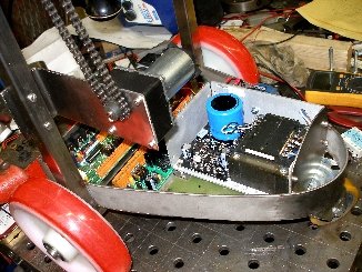
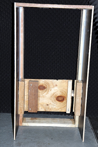
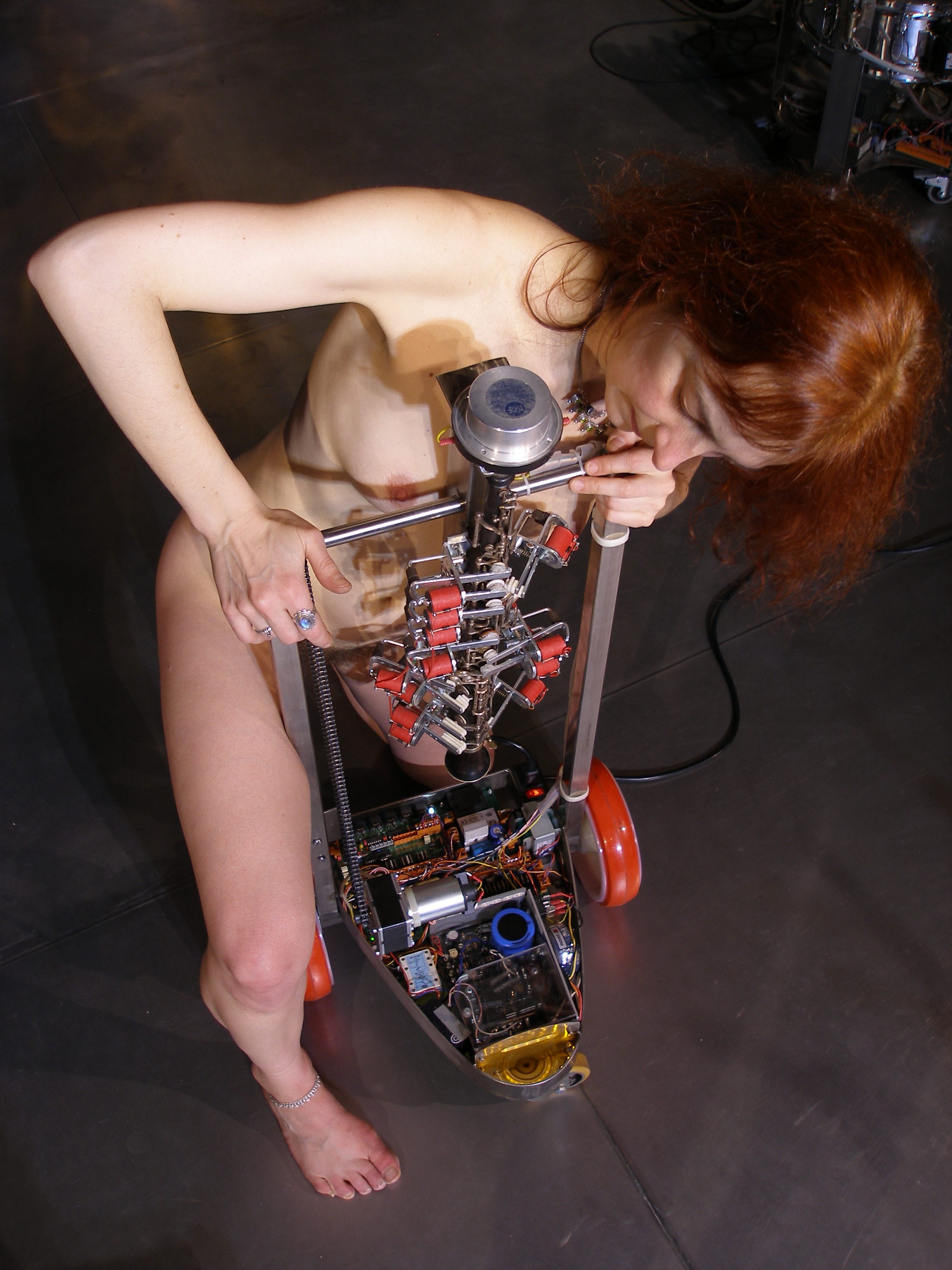
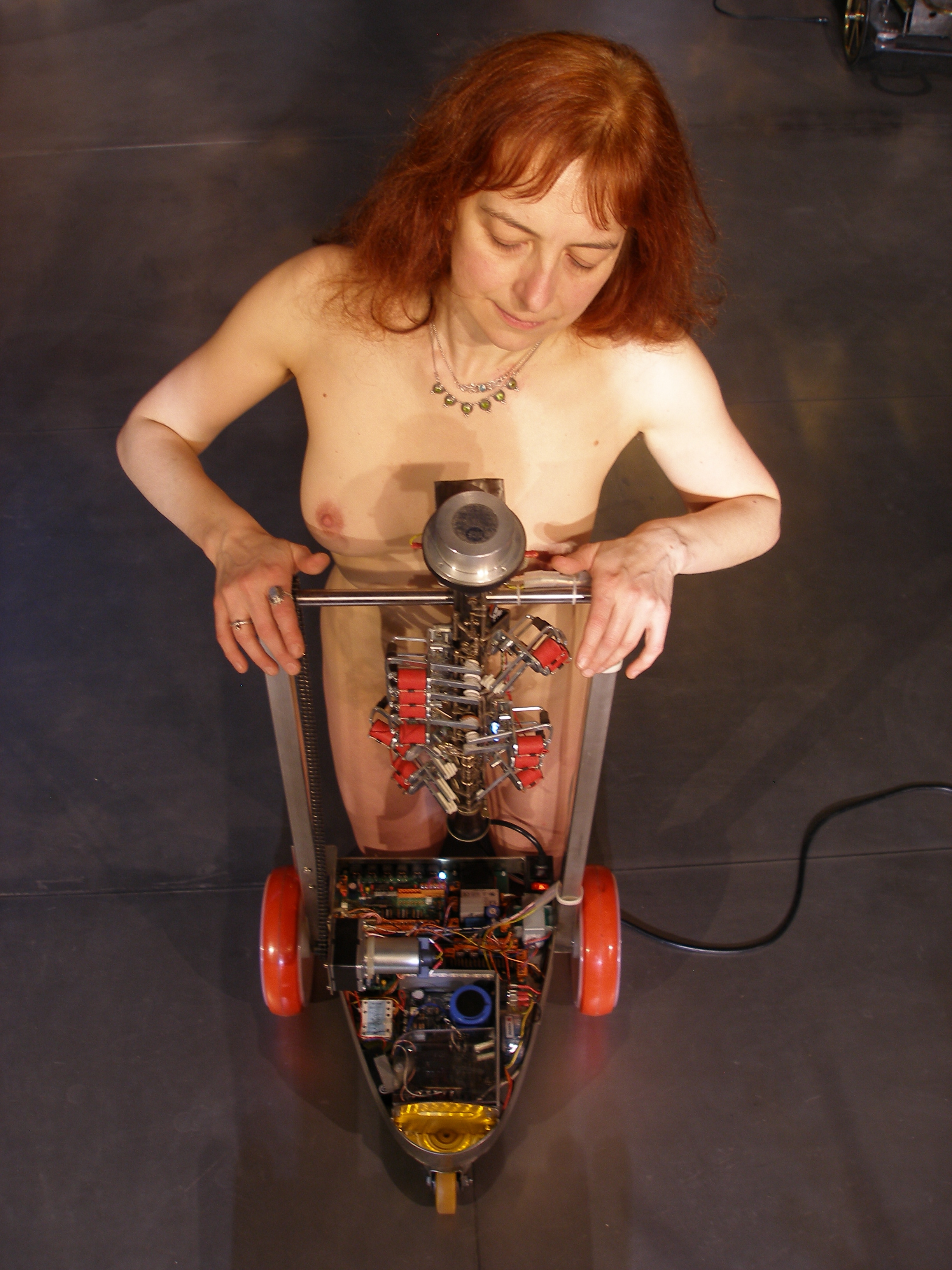
As an extra feature, we suspended the entire automated oboe construction in a cradle. Thus the instrument has freedom to move in different inclinations. The axis of suspension is provided with a dented wheel driven by a chain and a Crouzet DC motor with reduction gears. This way, any inclination can be held and controlled. The movement possibility was added since it mimics a bit the behavior of a human oboist. In the software we use for controlling the automaton, we are implementing rules such that the robot derives its gestural behavior from the music it gets to play. This feature however will be implemented in our GMT language and software environment, rather than in the firmware of the machine itself. The circuit secures that the instrument is not allowed to turn fully around, since that would ruin the robot. Movement is limited to an angle of ca. 90 degrees. In the first version we used mercury switches as sensors for the position, but these suffered a lot from double triggering. For version 2, we first tried using a new design using proximity sensors (Pepperl+Fuchs). Obviously the firmware had to be completely redesigned, but the results with these sensors where still unsatisfactory. Finally we decided to call in an analog tilt sensor by Penny & Giles (Type STT290/60/P2) allowing us the read the position of the instrument at all times using an analog input port on the PIC controller. For the motor control we made use of a Trident 4-quadrant DC motor controller:
 In order to facilitate
interactive applications, we provided <Ob>> also with a midi output
port from which the position of the oboe in its cradle can be read in at any
time.
In order to facilitate
interactive applications, we provided <Ob>> also with a midi output
port from which the position of the oboe in its cradle can be read in at any
time.
Finally, some light effects were added to the design as well. These are also
controlled by the midihub board, since this board had still plenty of outputs
available.
Only when integrated in the context of our Logos Robot Orchestra with its wealth of varied sensor systems allowing full interactivity, this automate becomes a true robot. That's after all were its destination is to be sought.
Midi channel: fixed to 14 (counting 0-15).
Note Off: Implemented for notes 58 to 96. Starts a short decay (release) on
the playing note. The duration of the release is determined by the value of
the controller 19. For legato playing, note-off's can even be dropped, since
the instrument is monophonic. Note-off with release is not implemented here,
so only controller 19 can be used yo this purpose.
Note On: Implemented for notes 58 to 96. Velo-byte is used for the level of the sustained sound portion. To steer the attack force, controller 17 must be used. Note that for this robot, the usual general volume controller (#7) is not implemented. The lights are also mapped on notes, but make use of the 0-5 range, outside the normal range of the oboe. For those lites the velo byte is implemented to make automatic flashing possible. The velocity value determines the speed of the flashing. With value = 127, the lites will be permanent on. With zero value, they will be off.
Key pressure (160 + channel, msb, lsb) is implemented to allow for alternative fingerings. msb contains the solenoid activation bits for the lowest 7 solenoids, lsb the remaining 6 bits/ solenoids on the high side. The mapping follows the wiring details given in the maintenance section at the very bottom of this webpage. The note aftertouch command should be issued immediately after a note on. It than will override the normal fingering. Key pressure commands can be sent during the playing of a note, thus rendering sound timbre effects possible as well as improved fingering for quartertone music. After a note off command, aftertouch will have no other effect than soundless key clicks. In fact, a noteoff will always release the finger-solenoids. Although only implemented for debug purposes, it might be good to know that midi note 0 will always release all valves. As such it is equivalent to sending 174, 0, 0.
| bytes | msb | lsb | ||||||||||||||
| hardware | D7 | D6 | D5 | D4 | D3 | D2 | D1 | D0 | D7 | D6 | D5 | D4 | D3 | D2 | D1 | D0 |
| midi-map | 0 | D7 | D6 | D5 | D4 | D3 | D2 | D1 | 0 | D0 | D7 | D6 | D5 | D4 | D3 | D2 |
Controller 17 is used to control the maximum sound level during the attack period.
Controller 18 is used to control the duration of the note attack. The interdependencies of these controllers together with the velo byte is shown in the graph below:
Controller 19: Release time. If legato playing is in use (meaning we do not send note-off's) the setting for this controller will be overridden. If you use sequencer software that does not allow you to not send note off's, legato playing can be obtained by setting this controller to values between 105 and 112.
Controller 20: Tuning. The basic tuning of the instrument can be shifted a
quartertone upwards. At setting 5 the tuning corresponds to A=440 Hz. (Precision
better than 1 cent).
Controller 22: Inclination controller. Value 64: downward vertical, 63-0= move
backward, 65-127=move forward. The full traject is ca. 90 degrees.
Controller 66: Robot on/off switch. On power down (ctrl.66 set to 0) the motor will bring the instrument back to a full verical position
Controller 123: switches the sounding note off, releases all keys, does not affect motor position, dims all the lights.
Pitch bend: The <Ob> robot can be used in any tuning system. Using the Midi Pitch Bend command, any playing note can be raised of lowered by a quartertone. Hence the full range (0-127) corresponds a semitone. The tuning returns to normal with the pitch bend set halfway (64). In the drawing below we give the coding example for a fragment of a quartertone scale:
 Most good sequencer
software (such as Cakewalk or Sonar) use the signed 14 bit format. Note that
one unit of the msb corresponds exactly to a 0.78 cent interval. To convert
fractional midi to the msb only pitchbend to apply follow following procedure:
if the fractional part is <= 0.5 then msb= 63 + (FRAC(note) * 128), if the
fractional part is larger than 0.5, we should switch on the note + 1 and lower
the pitch with msb= (1-FRAC(note)) * 128. Note off should
reset the pitch bend for the playing note!
Most good sequencer
software (such as Cakewalk or Sonar) use the signed 14 bit format. Note that
one unit of the msb corresponds exactly to a 0.78 cent interval. To convert
fractional midi to the msb only pitchbend to apply follow following procedure:
if the fractional part is <= 0.5 then msb= 63 + (FRAC(note) * 128), if the
fractional part is larger than 0.5, we should switch on the note + 1 and lower
the pitch with msb= (1-FRAC(note)) * 128. Note off should
reset the pitch bend for the playing note!
Program change: not implemented.
Lights: The lights are mapped on very low midi-notes as follows:
Midi output port: sends the actual position of the oboe as a 7 bit number, using the <Ob> midi channel. The format is that of a note pressure command. The pressure value corresponding to the angle of the instrument: 0= extreme inwards, 64= vertical, 127= extreme frontal. The data is only sent on changes of actual position. The midi output connector is the DIN outlet on the extreme right side of the hub board.
Technical specifications:
Design and construction: dr.Godfried-Willem Raes
Collaborators on the construction of this robot:
Music composed for <Ob>:
Pictures taken during the construction, maintenance and repair in our workshop:
| Back to Main Logos page:index.html | To Godfried-Willem Raes personal home page... | To Instrument catalogue |  |
<Ob>
Voor deze robot stond ons als doel voor ogen zo getrouw mogelijk
de werking van de traditionele hobo te mimeren. Het entoeziasme van mijn medewerkers
bij Logos voor zo'n projekt was nogal wisselend: van uitermate negatief en afwijzend
tot gematigd hoopvol. De suksesvolle automatisering van zo'n traditioneel geladen
instrument leek bij voorbaat tot mislukken gedoemd. We namen de uitdaging niettemin
aan en het lag, gezien het uitgangspunt, daarbij dan ook voor de hand te vertrekken
van een bestaand instrument in goede staat. Daartoe konden we beschikken over
een orkest hobo gebouwd door F.Debert in Brussel, vermoedelijk in de eerste
helft van de 20e eeuw. Ooit eens gekocht op de Gentse prondelmarkt.Afgezien
van de relatief ingewikkelde en weinig repetitieve mechanika, stelde de bediening
van de kleppen op zich geen nieuwe problemen. De krachten nodig voor het bedienen
van de vele klepjes zijn immers betrekkelijk klein. Niettemin zagen we af van
het automatiseren van elke voorhanden klep op het instrument, omdat vele ervan
slechts nodig zijn voor menselijke spelers. Zo zijn de drie hulpkleppen voor
de oktaven alleen nodig bij menselijke bespeling om de gewenste toon snel te
laten aanspreken. In ons ontwerp is dit evenwel gegarandeerd op grond van de
wijze van aansturing zodat we aan een automatisering van deze kleppen gerust
konden verzaken. Hetzelfde kan worden gezegd van de trillerkleppen. Waar mogelijk
maakten we voorts gebruik van de mogelijke maar door spelers eerder vermeden
vorkgrepen. Zo slaagden we erin de gehele applikatuur te automatiseren met niet
meer dan 6 elektromagneten voor de open toongaten en 7 elektromagneten voor
de bediening van de klepjes. De vereenvoudigde vingerzettingstabel kwam er dan
uit te zien alsvolgt: de gele lijntjes geven aan welke kleppen via elektromagneten
worden bediend.
Mikrotonaal
spel, inklusief kwarttonen zijn mogelijk door toepassing van non-standaard grepentabellen.
Alternatieve grepen kunnen trouwens ook worden toegepast om klankkleurvariaties
te bewerkstelligen. De hele opbouw van de elektromechanika voor het vingerwerk
was uitermate tijdrovend, maar toch niet bijzonder moeilijk. Het vereist wel
heel precies las-, tap-, boor-, zaag- en snijwerk.
De toegepaste
standaardvingerzettingen zijn als hexadecimale getallen weergeven in de rechterkolom
van de vingerzettingentabel. Dit is de wijze waarop de grepen-opzoektabellen
in de mikroprocessor worden geimplementeerd.
Anders daareentegen met het klankopwekkingsmechanisme: het dubbelriet. Onze
eerste experimenten gingen onmiddellijk uit naar de konstruktie van dubbelrieten
opgebouwd uit twee plaatjes piezokeramisch materiaal, gekleefd op messing blaadjes.
Het grote mechanisch probleem daarbij is dat het piezokeramisch materiaal zich
niet laat buigen (het is erg breekbaar) terwijl het riet, wanneer we de opbouw
van een traditioneel hobo riet volgen, in elk geval moet worden rondgezet rond
het kleine inblaaspijpje dat in het instrument wordt geplaatst in een cilindrische
kurken houder. Na ettelijke pogingen slaagden we erin een riet op deze wijze
op te bouwen. Aangesloten op onze frekwentiegenerator -beide riethelften parallel
geschakeld en dus elektrisch in faze en mechanisch in tegenfaze- bleek het nog
te trillen ook! Alleen, de geluidsopbrengst bleek ruimschoots onbevredigend.
We haalden hooguit een -voor een normale hobo overigens zo goed als onmogelijk
- pianissimo. Bovendien produceerde het riet ook bij bepaalde stuurfrekwenties
multiphonics die te wijten waren aan de eigenresonanties van de messingplaatjes.
De toon sloeg ook regelmatig over naar het suboktaaf. Opgemerkt moet worden,
dat we bij deze experimenten geen wind toevoerden aan het riet, vanuit de ervaring
opgedaan met eerdere koperblaasinstrumenten waarbij bleek dat de luchtverplaatsing
door het instrument eigenlijk niet wezenlijk is voor de klankproduktie van het
instrument. Ook het aanleggen van een sterk verhoogde stuurspanning (de normale
toelaatbare maximum spanning wordt in het datasheet opgegeven als 35V) bracht
geen soelaas. De dissipatie neemt toe maar niet de geluidsproduktie.
Een tweede reeks experimenten voerden we uit onder gebruikmaking van dubbelzijdige
piezoschijfjes. De amplitude van de trillingen is een veelvoud van die in het
eerste experiment. Dit schijfje werd passend en met een geringe aandrukkracht
aangebracht tegen een vlak geslepen dikke plaat messing die centraal werd geperforeerd
met een gat van 4.2mm, overeenkomstig de diameter van de hobo bij de inlaat
van het rietje. Via een opgesoldeerd buisje (7mm buitenmaat) kan het mechanisme
op de plaats van het riet op de hobo worden aangebracht. Voor windtoevoer moet
het geheel uiteraard in een potje worden geplaatst met een toevoer voor de lucht
en (luchtdicht afgesloten) voor de elektrische aansluiting. Dit mechanisme levert
voor bepaalde tonen een vrij goede klank maar blijkt in extreme mate frekwentieafhankelijk
te zijn. Ook is het aanspreken van de tonen erg afhankelijk van de aangelegde
winddruk. Het geluidsvolume -althans voor de goed aansprekende tonen- is heel
wat beter dan in het eerste experiment, maar toch nog te gering in vergelijking
met een realistische hobo.
Een derde reeks experimenten werd opgezet onder gebruikmaking van een tweeter
motor driver van RCA. Als koppelstuk maakten we daarvoor een akoestische impedantietransformator
gemodelleerd naar een menselijke mondholte met riet. Dit stuk, vervaardigd uit
massief messing, werd gedraaid op de draaibank. Dit is de maatschets:
De linkerkant is passend gedraaid om 12mm in de RCA motor driver te worden aangebracht,
zonder de inwendige titanium dome te raken. De rechterkant werd afgedraaid om
in de hobo te passen op de plaats van het riet. De betrouwbaarheid van de klankproduktie
is nu uiteraard perfekt, maar om de klank echt realistisch te maken blijven
heel wat modulatieparameters essentieel. De
golfvorm van de aansturing moet trapezoidaal zijn en frekwentiemodulatie (vibrato)
lijkt aangewezen. Bovendien draagt faze-modulatie van de eerste twee partials
boven de grondtoon wezenlijk bij tot het realisme van de klank. Ook enige mate
van amplitude modulatie (omhullende) blijkt noodzakelijk. Wat dit betreft sluiten
de resultaten goed aan bij de bevindingen opgedaan bij de bouw van <Korn>,
onze automatische kornet.
Een bijzondere eigenschap van <Ob> is dat hij ook kan bewegen. Daartoe
monteerden we de gehele draagstruktuur voor de hobo zelf op een 16 mm as voorzien
van een tandwiel waarop een ketting loopt. Deze ketting wordt aangedreven door
een DC motor met vertragingskast. De tandwielen en de ketting zelf recycleerden
we uit een oude fotokopieermachine. De motor dienden we evenwel nieuw te kopen
omdat die doorlopend van draairichting moet kunnen wisselen, iets wat met gelijkstroommotoren
kan worden bereikt door eenvoudigweg de poling om te wisselen. Hierdoor kan
<Ob> niet alleen schommelen, maar ook op eender welke hoekpositie binnen
een bereik van ca. 90 graden vastgezet worden. Iets van de beweeglijkheid van
de menselijke spelers werd dus ook hier geimplementeerd. Opdat er geen destruktieve
ongelukken zouden kunnen gebeuren, werd het schommelmechanisme aanvankelijk
uitgerust met vier kwiksensoren die het doordraaien van de motor moeten verhinderen
en het bovendien mogelijk maken het instrument zuiver vertikaal te positioneren.
Bij een latere upgrade vervingen we deze kwikschakelaars door een Penny&Giles
hoeksensor wat een veel betrouwbaarder resultaat opleverde.
Tot slot bouwden we ook in <Ob> enkele bestuurbare lichteffekten in, gemapt
op note on/off midi kommandos.
De volledige midi-implementatie is opgenomen in de Engelse tekst hierboven.
<Ob> luistert uitsluitend naar midi kommandos via kanaal 14.
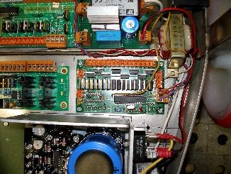
De elektronische schakeling bestaat uit enkele afzonderlijk funktionele boards:
1. TC/UPD en/of midihub board;
Dit board bestuurt de vizuele komponenten van deze robot: de slingerbeweging en de positie van het instrument evenals de diverse ingebouwde lichteffekten.
Het schakelschema voor de motor links op de
tekening was onze eerste versie. Als beschermingsschakeling werkte die echter
al te goed, d.w.z. wanneer een veiligheidsschakelaar werd bekrachtigd, werd
de motor stroomloos. Het probleem dan was echter dat hij met geen (elektronische)
middelen nog in beweging te krijgen was... Vandaar dat we in de tweede versie
opteerden voor een automatische omschakeling van de draairichting. Daarbij werd
beroep gedaan op een impulsrelais. Omdat de mikrokontroller nu evenwel geen
informatie heeft over de eigenlijke draairichting, voorzagen we in twee analoge
outputsignalen die kunnen worden ingelezen. Wanneer beide signalen positief
en hoog zijn, is de motor onbekrachtigd. Het ene signaal van beide dat laag
is, geeft de draairichting aan. Beide signalen kunnen nooit samen op massanivo
zijn, tenzij bij uitval van de motorvoedingsspanning zelf. De kondensator en
de diode werden toegevoegd om de stoorspanningen van de motorkollektor en van
het PWM signaal uit te filteren. De spanningsdeler staat er borg voor dat de
PIC ingangen nooit meer dan 5V te verwerken kunnen krijgen. Hoewel deze schakeling
toch bijna twee jaar heeft gewerkt traden er toch geregeld problemen op met
de kwikschakelaars die soms dubbele pulsen gaven waardoor het impulsrelais kon
gaan oscilleren... Een manuele nood ingreep bleek telkens weer noodzakelijk
om verder onheil te voorkomen... De derde en voorlopig definitieve versie (Ob
versie 2.0) werd opgebouwd onder gebruikmaking van een Trident 4-kwadrant DC
motor-kontroller: Dat
was niet zo eenvoudig als het lijkt omdat alle stuurspanningen bipolair en zwevend
moeten zijn voor dit type kontroller, wat de interfacing naar mikrokontrollers
erg moeilijk maakt. Eigenaardig genoeg zijn er erg weinig goede 4-kwadrant kontrollers
voor kleine gelijkstroommotoren op de markt (die van Maxxon even buiten beschouwing
gelaten want die zijn onnoemelijk duur...).
Het volledige schema van dit mikroprocessor board is weergegeven aan het eind van deze webpagina. Het UDP/IP ethernet board is volop in ontwikkeling. Als extra, werd op dit board ook een midi output voorzien die toelaat de juiste positie van de hobo in te lezen. De meest rechtste DIN konnektor op het hub board wordt hiervoor gebruikt en kan dus niet als midi-thru worden ingezet.
2. Kleppenbesturingsboard
De PIC op dit board, een 18F2525, staat in voor het juist toepassen van de vingerzettingstabel op de gevraagde te spelen tonen. Het PC board is hetzelfde als wat we ontwikkelden voor heel wat slagwerk robots zoals <Dripper>, <Casta>, Troms>, <Psch>, <Snar> e.a. De zestien beschikbare mosfet driver uitgangen volstaan voor het aktioneren van alle nodige kleppen: dertien. De firmware is uiteraard totaal verschillend. De Midi input (in TTL formaat) wordt toegevoerd vanuit het midi-hub board. De op de print voorziene 74HCT14 chip is niet gemonteerd. Details van het schakelschema zijn te vinden onderaan deze web-pagina.
3. Rietbesturingboard:
Hiervoor
konden we hetzelfde printontwerp gebruiken dat we eerder ontwikkelden voor <Aeio>
en dat gesteund was op prototypes ontwikkeld en gebouwd voor robots zoals <Korn>,
<Hurdy>, <Autosax> en <Bono>. Ook hier werd eenzelfde PIC
mikrokontroller toegepast: de Microchip dsPIC30F3010.
Pas wanneer deze automaat wordt geaktiveerd in de kontekst van het M&M orkest, waarbinnen hij vanuit een veelheid aan diverse sensoren en via doelspecifieke software kan worden aangestuurd, wordt hij een heuse robot. Daarin ligt ook zijn bestemming.
Construction & Research Diary:
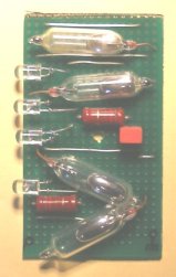
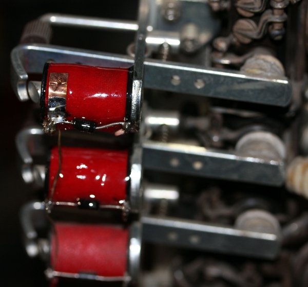
The picture shows the sensor assembly. The two mercury switches above are
for the vertical position sensing, the ones below for excursion limit determination.
The four LED's are just a visual extra feature. The sensor assembly is mounted
on the oboe carrier profile with a single M4 bolt. The hole in the carrier
is threaded. A 10 mm stand off should be used. Once ready and the exact positions
of the mercury switches are determined, they should be fixed in place with
some dots of MS-polymer or hot glue. This
circuit generates a floating bipolar voltage between the X17-2 and X17-3 terminals.
The 410 Ohm resistors are in fact each two 820 Ohm resistors connected in
parallel. We
are now at firmware version 2.7 for PIC1 on the midihub board. White LED spotlite
added, mapped on note 4. Now, waiting for user feedback and comment...
This
circuit generates a floating bipolar voltage between the X17-2 and X17-3 terminals.
The 410 Ohm resistors are in fact each two 820 Ohm resistors connected in
parallel. We
are now at firmware version 2.7 for PIC1 on the midihub board. White LED spotlite
added, mapped on note 4. Now, waiting for user feedback and comment...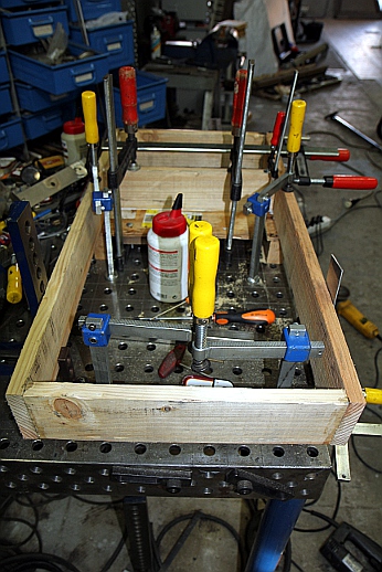
 De
spoel vervangen kan niet meer, want Laukhuff is inmiddels ter ziele gegaan.
De klepjes en zowat het hele mechanisme van de hobo blijken wat zwart te zijn
uitgeslagen. Is het verzilverd? Kunnen we dit verhelpen zonder de hele robot
te moeten uiteenhalen? Het wordt hoe dan ook een werkje waarvoor heel wat
geduld nodig is... Voor de klank maakt het evenwel niks uit.
De
spoel vervangen kan niet meer, want Laukhuff is inmiddels ter ziele gegaan.
De klepjes en zowat het hele mechanisme van de hobo blijken wat zwart te zijn
uitgeslagen. Is het verzilverd? Kunnen we dit verhelpen zonder de hele robot
te moeten uiteenhalen? Het wordt hoe dan ook een werkje waarvoor heel wat
geduld nodig is... Voor de klank maakt het evenwel niks uit. | (Terug) naar logos-projekten: | Terug naar Logos' index-pagina: | Naar Godfried-Willem Raes personal homepage... | Naar katalogus instrumenten | |
M&M orkest |
Last update: 2023-10-08 by Godfried-Willem Raes
The following information is not intended for the general public nor for composers wanting to make use of our <Ob> robot, but is essential for maintenance and servicing of the robot by our collaborators. It also might be usefull for people that want to undertake similar projects. Feedback is mostly welcomed.
Technical drawings, specs and data sheets:
Power supplies:
Wiring & circuit details midihub board:
Circuit details solenoid driver board:
dsPIC board - compressor driver:
Wiring for the dsPIC-board:  This is the same board as also used for <Aeio>, <Hurdy> and <Bono>.
Motor Specs:
Crouzet 80807001, 24 V, rap. :125, motor 3000 rpm. Geared 21 rpm. Farnell order nr. 308-9514. Current consumption without load @ 24 V: 300 mA. Lowest voltage required for rotation: 2.6 V. Price (01.10.2008: 217.90 Euro).
Toggle relay: ESDI type nr. NF-8250, 12V coil, contacts 16A 250V ac. Purchased at RadioHome Electronics, Ghent. [ removed 18.10.2010]Tilt sensor : Penny & Giles (STT280.60.P2) Data sheet. (PDF) [cost: ca. 250 Euro]
Mechanical construction drawings and welding plan:
RCA-driver:
Tweeter horn driver TW15W 8 Ohm. Cross over frequency by design: 800Hz. Peak allowable voltage: 10.9V, to be derated with 12dB/octave for the frequencies below 800Hz. Price in 1982: 2.360 Bef. (ca. 60€)
Yellow LED strips: LM-FB26Y-12, Farnell order code: 122-8819
Oboe details:
Builder: F.Debert, Bruxelles. Model C60. We have no indication as to the year of construction, but since the tuning conforms to A=440, we suspect it was made not much before 1939.
Download high resolution pictures of this robot:
Download high resolution robody pictures of this robot:
References:
Bartolozzi, Bruno, 'New Sounds for Woodwind' , Oxford University Press, London 1982 (1967), ISBN 019 318611-x
Benade, Arthur H., "Fundamentals of musical acoustics",
Dover Publications Inc., New York 1990 (1976). ISBN 0-486-26484-x
Goossens, Leon & Roxburg, Edwin "Hobo", ed.A.J.G.Strengholt's Boeken, Naarden, 1977 (1980), ISBN 90 6010 504-4 (This book contains the fingering tables for the oboe).
Raes, Godfried-Willem, "Expression control in musical automates", 1977/2023,
Smith, Bob H., "An Investigation of the Air Chamber of Horn Type Loudspeakers", in: The Journal of the Acoustical Society of America 25, 305-312 (1953); https://doi.org/10.1121/1.1907038
Weijers, Rembert, "Rieten ontwerpen en maken", Muziekuitgeverij van Teeseling, Nijmegen, 1978.