Gesture controlled virtual musical instruments
A practical report
dr.Godfried-Willem Raes
postdoctoral researcher
Ghent University College & Logos Foundation - Hogeschool Gent
- Music Department
1999/2002/2003/2004/2007/2009/2010
1.- Introduction:
All musical instruments are tools that map human motoric input on an acoustic output. In traditional musical instruments, the input-output mapping, fully characterizes the instrument and cannot be changed. Since the advent of electronics, it became in principle possible to map the input -on instruments having an electrically mediated input (such as in the case of most modern keyboard instruments)- on any sound producing device that in its turn can be controlled electrically. This is clearly the case for all electronic sound generators, but it also applies to a wide collection of electromechanical instruments, such as player pianos, organs, percussion devices etc.& ; (1)
In the present paper we will cover some aspects of our own research in input interfacing and design.
Thus we will concentrate on practical and experimentally tested ways of deriving a maximum of relevant information from human expressive gesture such that this information can be mapped on different levels of sonification in order to realize a user programmable musical instrument. We will introduce two systems we have developed and tested over a period of more than twenty years now:
Both these technologies make it possible to design an absolutely non-contact interface to capture motoric and thus gestural information. Other than with capacitive and optical systems, these technologies are inherently non positional and, more important even here, capable of delivering dynamic information straight away. (2) A condition for reliable operation of any device based on Doppler reflection of the body is that the performer ought to be nude. Clothing damps the reflection with at least 12dB and obscures precise detection of gesture.
1. Sonar:
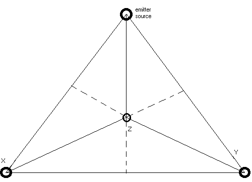
Continuous wave: In contrast to pulsed sonar technology, we have worked mostly with continuous wave sonar (and radar, as we will see further) technology. The transducers we have used in conjunction with ultrasound can be tuned to frequencies between 27 and 220kHz. (4) The operating frequency determines the frequency range of the received differential tones. The lower this frequency, however, the larger the area covered by the system. The higher the frequency, the higher the resolution will be. There is one emitter and three receivers each placed on the vertexes of an imaginary tetrahedron:
Set Up:

As to the dimensions, we took a size of 3 meters for the sides (a) . The reasons for this choice are:
The height of the tetrahedron now is : aÖ (2/3) = 2.449 m. If we allow for some margin for the physical size of the transducer and the suspending hook or fixture, this is about the maximum size that fits common architectural spaces. After all, we wanted to realize an instrument that could be played in as many spaces as possible. (6)
The inclination angles for the set up of the X and Y transducers must be 25° 15" (tga = (Ö 2)/3), since they should be oriented to the point of gravity of the imaginary tetrahedron. In order to facilitate setting up the instrument, we have build our transducers into a housing of exactly that angle. The Z tranducer is suspended vertically.
Operation principle:
Other than pulsed sonar and radar systems, these systems are based on the Doppler effect. For that reason they cannot as such be used for distance measurement.(8) Non moving objects do not cause a Doppler shift and thus remain unperceived. This is one of the main reasons to favor this system above others for implementations of musical instruments.
At point C we place an ultrasound emitter. The frequency of the sound can be anything between 22kHz and 200 kHz.
For ultrasound in air V is the velocity of sound (343 m/s). Ultrasound can be used very well in liquids: water, where another velocity applies. (Actually the practical use of ultrasound in liquids is even older than its use in the atmosphere, and one of our earliest implementations did in fact work only in swimming pools, not to say modest bathtubs ;).
The frequency of the fundamental of the highest Doppler shifted frequency component present in the spectrum of the demodulated signal received at point x, equals:
fdmax =fc * ( (Vmp * cos(j ZX))/V)
If we consider movement to take place in the plane formed by the three receivers (the triangle XYZ) , then an easy relation exists between the frequencies of the three received signals:
From:
We can prove that
fz = fx + fy
(ref.: Raes, 1990)
Or, pretty trivial, one of the transducers appears to deliver redundant information if we consider movement to take place in a single plane only.
However, we have been unsuccessful in deriving a mathematical relationship between the three signals at the one hand, in function of arbitrary 3-dimensional angular coordinates of the movement.
Prof.Fred Brackx of this university actually passed me a proof that it was impossible to derive the movement angle or -and thats what were are actually after- absolute velocity, unambiguously from the signals received. Of course if we know our position and the angles of our movement, we can very reliably operate within the instrument.
Analog electronic circuits:
emitter:
This device should deliver a pure and rockstable 40kHz tone with a frequency stability > 0.001 promil and amplitude stability > 1%. We designed a simple crystal controlled sinewave generator trimmed to optimal symmetry and minimal noise. The output power is ca. 0.5 Watt. We do not dispose of the required measuring equipment to measure the resulting acoustical power pressure. The radiation angle should be at least 60° . The temptation to simply use piezoelectric ultrasound transducers in self oscillating mode, had to be rejected because the drift is way too large.
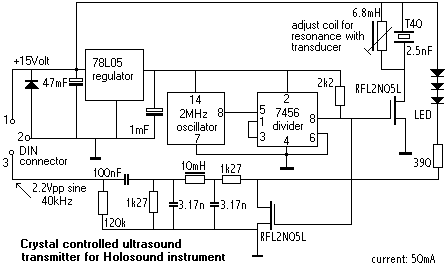
Note that in the circuit, we provided three LED's (blue light types) in series. These LED's emit pulsed light at the same frequency as the ultrasound. This element is used in our invisible instrument to detect the presence or non-presence of a person in the setup of our system, since this condition -as long as the person stands still- cannot be detected by the sonar on its own. The light is detected by a blue-sensitive photodiode set up in line with this emitter.
Receivers:
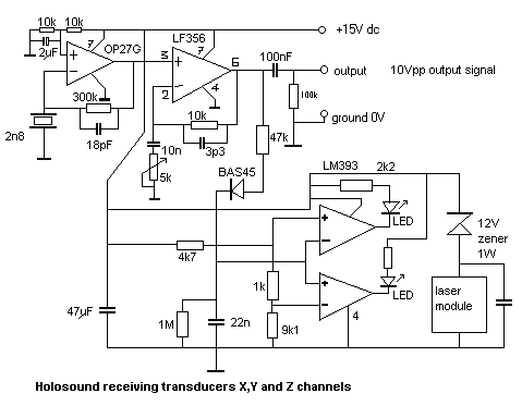
The design of the receivers is a lot more critical than in the case of the emitter. Here we have to cope with very low level reflected signals at the one hand and a need for a very good signal noise ratio at the other. The amplifier sensitivity has to be > 50m V and the S/N ratio > -66dB in order the end up with an 8 bit resolution. Of course we can limit the bandwidth, provided we can guarantee the amplifier to be linear within the frequency range of interest. This is pretty hard to do, when using piezo receivers with their characteristic non linear behavior around resonance. There are two distinct resonance frequencies, ca. 1.5kHz apart: one is the series resonance frequency, the other the parallel resonant frequency.
We found it possible to design a reasonably linear receiver, by using it in current source mode, i.e. connecting the piezo crystal between ground and the inverting input of an opamp. This way, the transducer is virtually short circuited and becomes almost linear within the frequency range of interest.
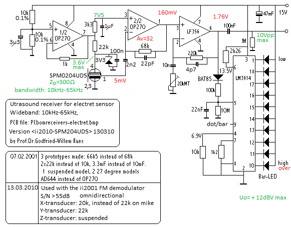
If users want the best possible sensitivity and linearity in response to movement velocity, condenser transducers should be used. Practical circuits tend to be more complex, because of the required high DC potential for the mike. Cheap solutions are possible by using MCE2500 type electret microphone capsules. They operate up to 65kHz with pretty good linearity, but a not-so-good signal to noise ratio. In recent years (2010) SMD elements became available with pretty good S/N ratios and omnidirectional characterists (Knowles Acoustics, type SPM0204UD5). Here is a practical circuit:
An extra feature of our receiver designs is that we provided them with window comparators to ease their set up. Ideally the three receivers have to be positioned exactly equidistant. To overcome the practical clumsiness inherent to realizing that in three-dimensional free space, we measure the signal amplitude received at rest and adjust this such that all three receiver signals produce exactly equal signals. More even, the comparator circuit allows us to position them exactly between nodal points of the carrier wave if we use the software utility we wrote whereby we can read out the phase of the carrier signals. The signals on the outputs of our X,Y and Z sensors (recorded for a carrier wave of exactly 40.000Hz) look like:
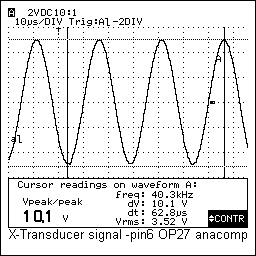
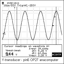
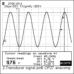
The laser module shown in the circuit drawing is mounted only on the Z-channel transducer. This transducer is suspended such as to form the top vertex of the tetrahedron. Thus the laser provides a visual indication of the center position for the player. These signals received by the transducer can be described as consisting of the following components:
a. the carrier wave
This carrier wave will at all conditions be the strongest part of the signal, since it is barely conceivable that a reflected signal could ever be stronger than the direct signal. Due to phase reversals and very low frequency phase shifts, due to movement as well as to interfering factors such as temperature gradients and air flow, however, this component is not constant in amplitude.
b. the Doppler shifted signals
The second component is a sum of signals of the form:
Ud(n)= Vr(n) * cos(w (n)+ j (n))*t
for all frequencies between fc and fd_max. The Doppler frequency with the highest frequency corresponding with the fastest moving part of the body is here defined as fd_max. All lower frequency components must be thought of as intrinsically present in the signal, since humans cannot detach parts of their bodies and thus any moving body part is connected to a (nonmoving) part of the body. Here we are considering movements such as arm-waving. Only if the complete body is moving, we could have a gap between fc and the lowest frequency shifted component in the signal. Then we could specify f_min and f_max delimiting the bandwidth of the Doppler shift. Note that the terms Ver(n) are relevant and correspond to the size of the body surface moving at velocity v(n). The phase factors are different with each spectral component since they depend on the relative position of the moving point considered as compared to the wavelength. As a consequence, it follows that some sort of more detailed 'vision' using Doppler radar must become possible: bodies are continuous 3-dimensional objects -there are no relevant 'gaps' or wholes- and these phase relations must hence reflect the shape of the body in movement. As long as we do not consider the information contained in the phase relations in the spectral bands of the signal, we will be limited to returning information on 'moving globs of stuff', sort of amoebas.
analog computer:
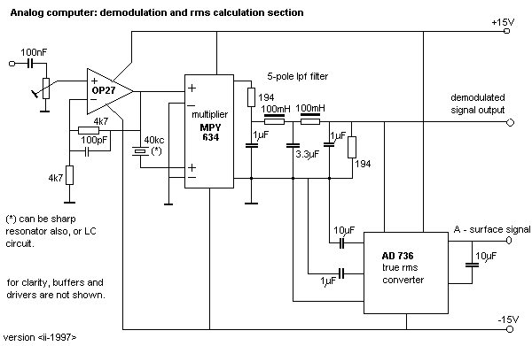
In this circuit, the three receiver signals as well as an image of the carrier signal, are brought together for signal conditioning and front end processing.
It would be very fashionable to not use analog circuitry at this place, and rather feed the signals directly to an ADC board and process the signals using DSP technology. Until now we have not done so in this area of our research. First of all because the signals were are processing are in a range necessitating sampling rates in the order of 100 to 500kS/s, to be multiplied by the number of data channels (3 in this case). That makes ADC converters very expensive. Consequently, the amount of data to be processed appeared to be overwhelming. Some calculation revealed that with available technology, real-time operation would become problematic. However we do not exclude that future developments lead us to port the analog computer to the digital realms.
The very first task we confined to the analog computer, consists of the demodulation of the receiver signals.
Our idea here was to perform both amplitude demodulation and frequency demodulation on these signals on order to derive information about the velocity of the movement as well as about the amount of moving body surface.
High precision multipliers (Burr Brown MPY634 etc.) are used to this purpose. They calculate for each channel the product Uc * Ux / 10 in the time domain ,which is the same as calculating sum and difference frequencies in the frequency domain.
In an earlier implementation ('Anacomp', 1992) we derived the Uc signal from the crystal controlled oscillator controlling the emitter. We than often encountered problems with slow phase shifts leading to quite large DC level shifts in the output. In the most recent circuits ('Diana', 1995), we derive the Uc signal by extracting it from the receiver signals directly, by using a very steep bandpass filter build with crystals tuned to the carrier frequency. (Precision phase locked loop circuitry can be used as well). The phase relation between Uc and Ux is now always constant. The demodulation becomes synchronous. A welcome side effect achieved by this approach is that without realizing it at first, we added a high pass filter function eliminating most involuntary movement related signal components.
Note that, in the conversion through the demodulation algorithm, the sign gets lost! We cannot tell anymore, from the signal, whether a movement took place towards a transducer, or away from it. It is conceivable though, to separately demodulate the upper sideband and the lower sideband and comparing both spectral densities, to make a decision as to the sign. If we have movement away from a transducer, the frequency should shift below the carrier, if we move towards it, it should shift above the carrier. However, many practical as well as theoretical issues compromise this idea: the design of analog demodulators discriminating intervals musically speaking in the range of less than a quarter tone , necessitates filters of very high orders which are virtually impossible to build. Furthermore, movements are rarely as simple as what we gave here as an example. Practically speaking, different parts of the body counterbalance movement direction in one sense, by moving in the opposite direction. As a consequence the Doppler shifts are never exclusively above or below the carrier. At this point there is work for further investigation.
After this combined FM/AM demodulation, we feed the signal to a steep bandpass filter with following characteristics:
highpass: @0.5Hz (to cancel out involuntary equilibrium movements)
The signal at this point, for two different movements, one moderate and another very fast, may look like:
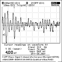
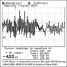
This first set of three signals -after normalization to a unipolar range of 0-10Volts- are brought to 3 output channels that can be read by the processing computer. Since there are no spectral components higher that 600Hz present in this signal, it can be sampled without information loss at a relaxed pace of 1200S/s. (Since 5m/s is about the absolute maximum speed, and we do not expect performers to play using movements that fast and grotesque, one can easily halve these values, sampling rate and lpf-frequency, without really loosing information).
But, more is and can be done, by our analog computer!
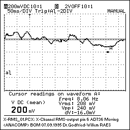
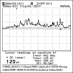
To extract information about the amount of moving body surface, we perform true RMS rectification (again using a dedicated analog computing chip) and integration (50ms time constant) on the filtered signal obtained so far. The thus obtained signals reflect the vectorial envelope of the gesture:
Ux = k* Sx * cos (ax)
Uy = k* Sy * cos (ay)
Uz = k* Sz * cos (az)
Note that only when the moving body were a sphere, we would have Sx=Sy=Sz. There seems to be no mathematical way to derive the mass of the moving surface from these equations, even though the angles ax, ay, az are related. However a system of special cases can help us out to a certain extend. This is handled through the software.
Although non-positional, the system is directional and vectorial: the player must thoughtfully control the angles of his movements, such as to make at least one of cos(ax), cos(ay) or cos(az) equal one.
The signal presented at the output of this processing step -shown for two timebases a decade apart (50ms/div versus 500ms/div , may look like:
A next analytical task performed by our analog computer consists of the calculation of a signal proportional to the vectorial velocity of the movement. For this we again start from the low pass filter following the multiplier. Here we feed the signal to a zero cross detector and a change pump. Note that it would be nonsensical to use a frequency counter here since the signals we are coping with are in no way periodic. The charge pump charges a capacitor functioning as a leaky integrator. The DC signal over this capacitor now reflects the spectral density of the input signal and for that reason is proportional to the movement velocity. In practice we have implemented this principle in a number of different ways: the simplest being a tacho-circuit, the most elaborate using three PIC controllers (Basic STAMPS actually), one for each channel. The tacho approach does work indeed as announced but has the disadvantage, that it behaves asymmetrical to changing input. It reacts very well and fast to increasing velocity, but very slow to the opposite. This compromises derivation and recognition of collision movements that are characterized by a sudden standstill.
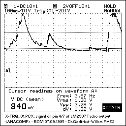
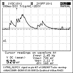
Further signals that are derived through analog computation are:
Combination signals: the largest surface value, the average surface value, the highest of the three velocity values.
All these elements are computed in our analog computers although since recent computers are becoming more powerful, it now should be considered no longer economical to spoil that many ADC channels on tasks with a very easy achieved software equivalent. For the most recent implementations, common industrial 8-channel ADC cards (12 bit resolution at 100kS/s is enough) suffice.
In our second analog/digital implementation (the version used for 'A Book of Moves', 1992/93) most of the processing was done on this analog computer. We used all 16 analog output signals, and had them simultaneously sampled by a 16 channel 12-bit ADC converter card residing in an ISA slot on a laptop PC computer. Since 2000 we use either a fast USB ADC-device or a PCMCIA-DAQ card by National Instruments, under Windows NT, and have only 9 channels to sample: 3 LPF-signals, 3 true RMS signals and 3 tacho signals. In no way our research into gesture controlled instruments should be considered as finished. We are indeed constantly improving both the analog computing aspects as the software, so this article can hardly represent the latest state of developments in this area.
In 2007 we started a project whereby we try to drop most analog processing and the very expensive precision electronic circuitry going with it. Here we are aiming at an implementation using DS-PICS, sampling the signal at exactly 4 times the carrier frequency (so for 40kHz, the sampling rate should be 160kS/s at 16 bit resolution for each of the three channels. The software can now determine the Doppler shift by calculating the phase slip difference of the signal versus the carrier. One of the advantages of this approach is that we can easily distinguish the direction of the movement as seen from the transducers by looking at the sign of the phase difference. The amplitude of the signal, as in the analog version, is the running average of RMS values of the signal after multiplication with the carrier. The new version should have its outputs send to the PC using a network UPD/IP protocol, thus making us less dependent on specific hardware.
In 2009 we ported most of the original design to a platform running under Windows 7 and using National Instrument's NI USB-6212 DAQ devices (16 channels, 16 bits, sampling rate up to 400kS/s). The analog multipliers remain, but their output (3 channels) is sampled directly and all data processing is now handled in software. On a quad-core pentium PC, we now can perform real time FFT's of the incoming signals and analyse the received spectra. In 2010 we made a system using a normal sound card: Holosound ii-2010.
2. Radar:
If continuous wave radar is used, the setup (and the math) is slightly different, in that we use Gunn diodes as both emitters and receivers (mixers). In principle it would be possible to use the same setup as we did for sonar, but problems with availability of wide angle radiators in the gigacycle range and noise as well as stability problems with the receivers, made us change the design.
So here we use 3 different microwave devices at frequencies that need to be only slightly different. The difference only needs to be larger than the anticipated dopplershift frequency range.
Vpm = peak velocity of the moving surface
Set Up
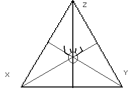
The frequency of the fundamental of the highest Doppler-shifted frequency present in the demodulated signal received at points x, y and z, in this case equals:
fdmax = 2 * Fc * ( (Vpm * cos(j x)) / c)
For a common frequency such as 12GHz and a maximum movement velocity of 5m/s this yields 400Hz. The analog computer used for the signal conditioning of the radar derived signals is simpler than in the case sonar is used. This is because the demodulation here takes place in the microwave devices themselves, and we are left with nothing but very low frequency signals. The principles however are the same: we also use true RMS rectification and integration to obtain surface related signals as well as tacho converters for the derivation of velocity information.
Comparing both technologies in this context -and of course telling from our experiments with the components we had at our disposal- we can conclude:
1.- Microwave systems perform inherently faster than their sonar counterparts. This is mainly due to the difference in the propagation velocity of the medium. Any sound wave, in order to be reflected and be received by our transducers, takes at least (2*Ö 2)/(3*Ö 3) * 3m / 343m/s = 4.76ms.
- The radiation is not blocked off by walls
- they are not dampened as much by their travel through space
- the systems are extremely sensitive to disturbances caused by ionizing sources (electroluminiscent lights.)
- in principle one needs a special permit to operate them
- it is very hard to stabilize their output amplitude.
- Their polar pattern shows many sidelobes
3.- Sonar systems are disturbed by airflow's (7), temperature gradients in the space (8), moving audience, fans and air conditioning devices, leaking gasses and breaking glass...
4.- For both systems, it would be much better to be able to use frequencies of say a factor 5 higher, since that would greatly relax the design of the integrators both for moving surface derivation and velocity derivation. In the case of sonar we are limited by the required power levels at high frequencies (the damping through air becomes excessive), in the case of microwave we simply couldn't get devices operating in the 77GHz range. Furthermore, for both technologies we have not found a solution as to the required polar pattern of the devices.
The end sum so far, made us go mostly for the sonar technology. An important extra feature -important from the perspective of traveling musicians- being the size (and weight;) of the equipment! Sonar can be made really small.
[ Note dd.. 01.2003: the author has a newer report with regard to microwave devices available: Quadrada.html]
[ note dd.. 2004: for more recent reports, cf.. Our report on the straight midi-outputting PicRada devices]
No matter what technology is used for the interfaces front end, the next issue is what to do with the obtained signals.
Although as such the demodulated signals can be and have actually been used as musical instruments (cf. 'Holosound', 1984, 'Slow sham rising', 2000) as well as in audio-art installations, by feeding the demodulated ac signals directly to a set of loudspeakers, they do sound more or less like a magical 3-dimensional super thundersheet;. Its all very impressive and extremely responsive, but far from musically versatile.
Hence the next step.
The software
Our first major pieces/instruments demonstrated a wide variety of ways of mapping data on musical parameters and entire structures. Sections such as 'Solo' and 'Minor' from our <Book of Moves> (1992) demonstrate this clearly. In that project, we mapped the movement data via extensive but very goal and composition specific software on midi controls for an external synthesizer module.
A next and further step was to use the information to control the real time audio processing of the simultaneous vocal input of the performers: this lead us to <Songbook> premiered in1995.
Since than, a major breakthrough in both precision and response time was achieved by making use of 'timeframe' technology: Here the software provides in a circular databuffer filled with readings from the ADC converter board. This memory buffer should be large enough to cover 4 a 5 seconds of real time data. The size is rounded to the next power of 2. In the version used for <A book of moves>, we had a 32kByte buffer: 16 channels x 256 s/S x 4seconds = 32kByte. (12bit data, or word aligned). In more recent software, we are using only 8 channels, but we are using higher sampling rates, so that our buffer is still only 64kB. (8channels, 1024/s,4",12bit=64kB). This circular buffer can be accessed for integration, spectral analysis, pattern recognition; in short everything we need to turn the raw and/or preconditioned data into some form of input-gesture related information.
Many different techniques can be used for the sampling. The cheapest and most elementary boards have no or very minimal internal RAM-buffers nor hardware programmable timers. The user has to perform periodic sampling through software. This can be as simple as defining a task with a period of 1024Hz operating on a global allocated memory buffer:
STATIC lptr_x AS WORD PTR
@lptr_x = ADC(n) ' ADC() would be the low level procedure to read the data
INCR lptr_x
Lptr_x = lptr_x AND &HFFF
But, a word of warning should be placed here: programmers all too often are mislead by a belief in timing accuracy of their software! However, no matter what language you use to write your code, nor what compiler you use, real periodicity cannot be obtained with normal PC's without special hardware. Jitter on obtainable sampling periods can be very severe (> 25%) and can only be estimated by external tools. Therefore we do prefer to use hardware sampling and timing and hence rather go for ADC cards using internal timers and block memory transfers from internal FIFO's to PC memory. National Instruments has proven to be a very good source for reliable DAQ devices.
The timeframe technology used for these newer versions and implementations of this instrument is based on a concept of tracking the past within 2 to 4 levels of time in the context of a fast multitasking program (<GMT>,(9)). The bottom level is that of immediate perception: the basic filtered data acquisition in real time as converted by the ADC's: the primary data buffer. It offers perfect immediateness and thus extremely fast response on changing input conditions, but no context at all. A basic sampling rate of 1024 Samples per second and per channel (we have only 3 data-channels with demodulated unprocessed information) is enough to cover any imaginable human motoric input. It will be obvious that this sampling rate and the buffer size was chosen to facilitate calculation of spectral transforms on the data buffers.
The model is depicted in the following sketch:
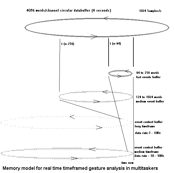
The first ring shaped timeframe analysis buffer covers a variable length section of the continually updated data found in the main ring buffer. This buffer is used for very fast spectral analysis after application of very simple windowing, as well as for filtering and integration. It is essential to cover collision gestures in the input fast. The size of this buffer can be dynamically adjusted in function of previous data and results if required. The result of the integration (or low pass filtering) of the contents of this buffer are put in another memory array, depicted at the bottom of our drawing. In this array, serving as a medium scale event context buffer, the data refresh rate needs only to be between 10 and 50Hz. This buffer is used for gesture-type analysis using fuzzy logic pattern recognition procedures as described further. With nowadays computer memory (remind you: we first developed this technology on small dedicated microcontroller systems;), there is in fact no longer a real need to make use of a circular buffer here: a full hour of memory taking up only 360kBytes.
The second ring shaped timeframe analysis buffer again covers a variable length section of the main buffer. In this case the timeframe is set to 1/8th " to 1". About 10 times a second, this buffer undergoes a complete analysis but this task does not have a very high priority in the multitasker. (Even on a 400MHz Pentium II, 3 DFT's on 1024points cannot be calculated without real-time performance penalties;). This is the buffer we use for attempting to derive potential periodic components from the gestures, such as tempo and rhythm. Until now we have to confess that we have not been able yet to reliably derive meter information from gesture such that we could apply it to real time implementations of 'conducting'. The principle does work, but it appears to lag way to much to be practical.
Just as in the case of the 64-256 buffer, here again we copy the analysis results obtained from this buffer, in yet another array updates 3 to 10 times a second. This becomes our large context buffer. It allows us to track accelerando and ritardando in the gestural sequences and such more.
Further, and particularly much longer timeframes can of course easily be implemented but appear to be irrelevant for real-time application, although they might be of interest to some concept of musicological science, since they would allow for general music performance analysis. We have not, as yet, performed much research in this direction however.
The technical advantages of this approach should be clear: we never have to deal in our software with calculations on very large data-sets which would slow down the real-time processing. DFT's are calculated on never more than 1024 points and 256 points or higher order timeframes, which is within the reach of real-time processing on the Pentium platform even when properly used compiled basic is the programming language of choice.
A very important consideration however is that as many independent processes as possible should be performed by their own thread or even -in later multiprocessor implementations- hardware: separate programmable timers, DSP-programmable multichannel ADC-board with some 512kByte buffer memory, and a precise state of the art analog computer front-end.
Typology of gestures with relevance to implementations of musical instruments using our holosound interface:
In the following the notation Ax,Ay, Az stands for: the integrated amplitude signals proportional to vectorial moving surface. Vx,Vy,Vz, for the integrated vectorial velocity information. The square brackets mean that the three vectors are seen in some functional combination, not further specified here (examples: the result of a MAX, PEAK, Average, Boolean OR function).
The indices tn, t(n+1) refer to time.
Fluent moves
Characterized by: constancy of velocity as well as moving surface within the timeframe considered
[Vx, Vy, Vz] tn = [Vx,Vy,Vz]t(n+1)
straight line segment moves
circular segment moves
for each type we can measure quantities for velocity as well as moving surface.
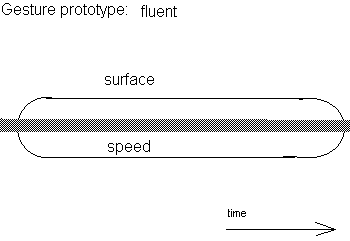
Expanding moves
Characterized by: the amount of moving surface is increasing within the timeframe considered
[Ax, Ay, Az] tn < [Ax,Ay,Az]t(n+1)
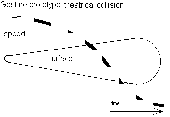
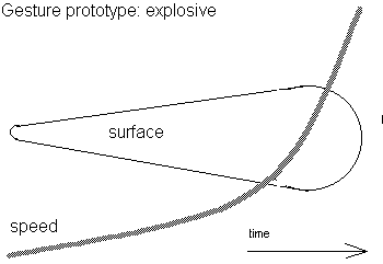
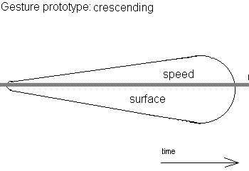
Contractile moves
Characterized by: the amount of moving surface is decreasing within the timeframe considered:
[Ax, Ay, Az] tn > [Ax,Ay,Az]t(n+1)
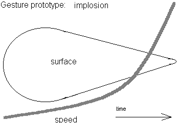
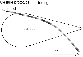
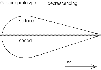
Closed moves
Characterized by a clearly marked beginning and ending. We can consider them as movement sentences. There are many shape possibilities here and it comes in very handy to use the prototypes of sentic form as developed and defined by Manfred Clynes. The timeframe considered should be not shorter than 500ms and not longer than 5 seconds.
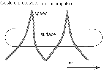
Percussive impulse
[Ax, Ay, Az] tn < [Ax,Ay,Az]t(n+1) > [Ax,Ay,Az]t(n+2)
[Vx, Vy, Vz] tn < [Vx,Vy,Vz]t(n+1) > [Vx,Vy,Vz]t(n+2)
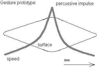
More difficult to recognize are types of gesture whereby the amount of moving body surface remains pretty constant, but the velocity changes within the timeframe of interest:
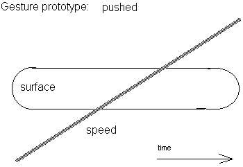
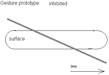
In order to classify the actual timeframe buffer contents into one or another category of gesture belonging to the above categories, we have experimented a lot with fuzzy logic procedures.
However, experience learned us that it is very hard if not impossible to provide general form determination software, at least if we want to get a bit further than recognizing 3 inputs: standstill, leaving the setup and entering the setup. So far we always wrote our software 'on the moving body' of a given performer. It should be possible however to write some sort of learning program to automate this very essential step. (Cf. Handwriting recognition problems). Probably we would have to first design and build some kind of programmable robot to perform gestural prototypes in a repeatable way. The way we worked so far makes it very awkward to find out whether failures with regard to 'recognition' are due to noise and software induced errors, or, to non identical input conditions.
dr.Godfried-Willem RAES
Notes:
Research & maintenance history:
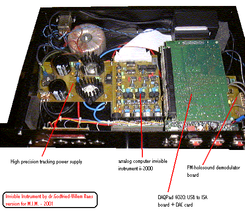
2003: software support under <GMT> highly improved. The invisible instrument can now also be used as a controller for the entire M&M robot orchestra.
_______________________________________________________________________
Ideally the dimensions of the tetrahedron should be made to depend on the body length of the player. Experiments and measurements lead us to propose the following practical formula, wherein L= body length of the player , a= ideal size of the tetrahedron side:
2L /3 = aÖ 2 / 3Ö 3 wherefrom: a = L 2Ö 3 /Ö 2 = 2.449 L
This gives for a person measuring 1m78 , a tetrahedron with a side of 4.36 meters. Its height would than be 3.56 meters, or larger than the height of a ceiling in an average architectural space. Calculations of the minimum size are based on the low rest position of the hands (these are at ca. 4/9ths of the length) given the practical formula:
a= L 4Ö 3 / 3Ö 2 = 1.633 L yielding, for the same person, a side of 2.9 meters and a height of 2.37m.
7. Airflow dependencies
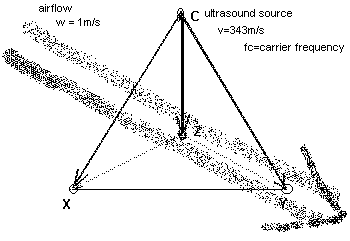
Air currents are causing Doppler shifts by themselves, since they do affect the propagation speed of sound. Wind carries sound, as common sense experience will tell. Obviously, when our bodies are moving, they will cause air currents as well. These are not a major nuisance however, since these effects are closely related to the information we are trying to gather. Constant wind flow or turbulence unrelated to our body movement, does cause errors in the system.
When using the instrument in the open air, these effects are very noticeable and they contribute a great deal to the degree of unreliability of the instrument. Inside buildings, we only have to cope with these effects when the space is equipped with venting systems (fans and air-conditioners). Most often it will be possible to minimize these effects by making sure these appliances are switched off during the performances. Doors and windows must be kept closed as well.
Fdif = [(v + w - vo)/(v+w-vs)]* fs
w = wind velocity in the direction of the soundwave
wv = w_air * cos (blowing angle)
T= temperature in Celsius degrees
Calculation for some very common ambient temperatures yields this table:
|
v @ 18° C |
341.729 m/s |
|
v @ 19° C |
342.315 m/s |
|
v @ 20° C |
342.900 m/s |
|
v @ 21° C |
343.484 m/s |
|
v @ 22° C |
344.067 m/s |
We can easily see that fluctuations in air temperature limited to +/- one degree Celsius, already lead to variations in the velocity of sound of 1.17m/s, or ca. 0.3%. The effect on the wavelength of a ultrasonic carrier wave of 40kHz can be calculated as:
l @21° C = 343.484 / 40000 = 8.5871 mm
or, a difference in wavelength of 0.03 mm. Gradients in temperature can have a quite strong influence on the dopplershift captured by our transducers. If we estimate a worst case temperature variance to be +/- 1° C , we can derive the worst case Doppler frequencies due to this effect as:
D f_high= (344.067 /342.900) * 40000 = 40136Hz
or, a frequency range of no less than 272Hz!
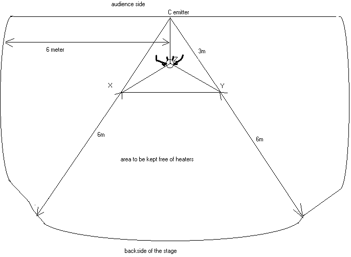
This is obviously a worst case scenario. It must be noted however that placing the Holosound setup too close to convection devices or air conditioners, makes the instrument virtually unplayable (uncontrollable...) as we have experienced all too often. If one encounters heaters on stage they should be either switched off, or the minimum distance between these and the closest point of the tetrahedron delimited setup in the direction of the emitter should be 6 meters.
Although this seems easy to realize, we have to put a warning here, since we often forget that theater spotlights function just like heaters! They actually radiate more heat than light, and thus we should also consider their effects.
<GMT> is a piece of software (a programming environment) we wrote specially for real time interactive algorithmic composition under the Win32Api on the Wintel platform. It can be obtained freely from our Internet site at URL: gmt_manual. It is written in the most readable of all structured programming languages: Basic. The compiler used is Power Basic's Windows compiler, version 8.00 or later.
(8): Distance measurement and determination using doppler radar and sonar devices is in fact possible, but requires frequency modulation of the carrier wave. The phase difference between modulating signal and the received modulated component of the carrier yields information on the distance to the reflective object within sight of the radar. Another technology we have worked out in 2010, long after the writing of this text, consist of a combined radar/sonar systems allowing very precise distance measument due to the difference in propagation speed of radar and sonar.
(9): note added in 2010: Recently quite a few ultrasound microphones became available with omnidirectional characteristics and wide band operation. They make use of MEMS technology. This makes FM modulation schemes a lot easier to implement and also makes the tetrahedral setup less stringent.
Bibliography:
Tilli, T 'Fuzzy Logic', ed.Kluwer,Deventer 1995
|
Further reading: article about invisible instruments |
To/back to Logos Duo |
||
|
Pictures NEW |
Last updated on 2019-12-19 by dr.Godfried-Willem RAES