<Holosound ii2010>
a doppler sonar based 3-D gesture measurement system
by
dr.Godfried-Willem Raes
postdoctoral
researcher
Ghent University, Ghent University College & Logos Foundation
2010
This technical note is a continuation of reports on many earlier designs for gesture sensing apparatus using both sonar and radar technologies. References to earlier designs are given in the reference section below. (1)
In this note we merely document the circuitry developed as an improvement of our 'Holosound' system, dating back from 1978 and updated in 2000. Hence the title, Holosound 2010. The design philosophy has been treated in depth in my writings on the 'Invisible Instrument'.
Main modifications over previous designs are:
1- the transducers in use here are omnidirectional wide band sensors operating in the ultrasound range.
2- the new circuitry supports FM modulation of the base frequency, thus allowing distance measurement as well as a variety of analog audio applications.
3- the circuitry can be used as such for audio installation projects and music theater compositions, but for gesture analysis, the outputs should by sampled and further analysed by a computer. Other than in our previous designs, here no special and expensive hardware is required. Earlier systems invariably made use of National Instruments data acquisition hardware. This version requires up to six audio input channels on the PC, although even with a common stereo input, the system can be used, be it restricted to two dimensions.
4- The signal/noise ratio has been improved with ca. 12 dB over earlier designs.
5- We introduce the combined application of radar and sonar technology in order to achieve full gesture imaging, including positional information.
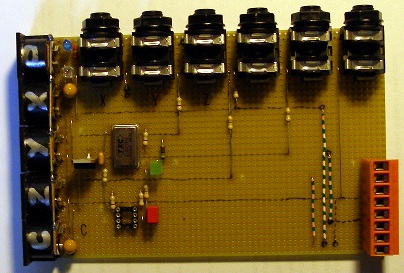
Receiver circuits (three are used in a tetrahedral setup):
Although the highest possible doppler frequencies for human bodies in movement using a 40 kHz carrier system are limited to less than 2.5 kHz (2), we designed these receivers with an output bandwidth up to 16 kHz. This was done to allow frequency modulation schemes as well as capturing of ultrasonic components in audio input in general.
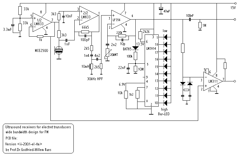
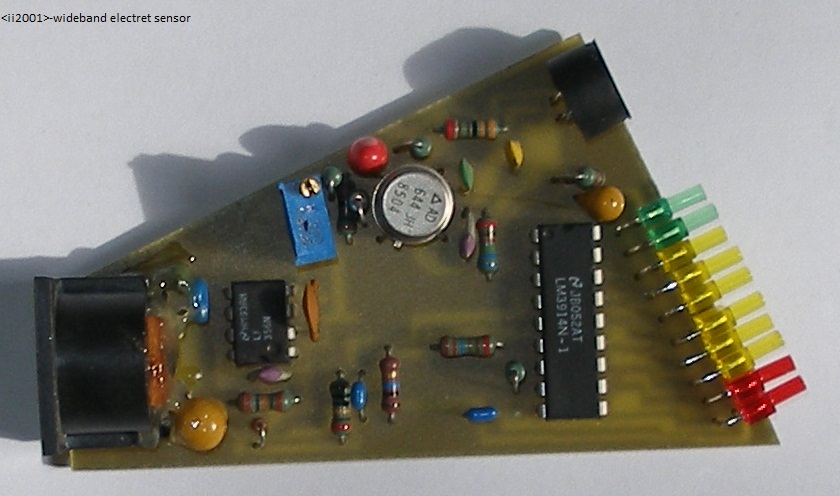
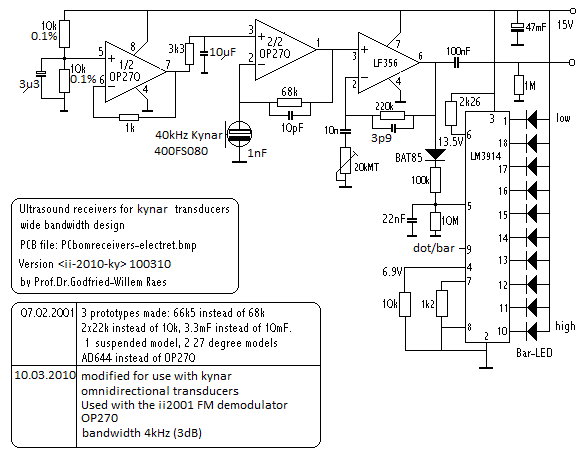
This became the sensor system of choice, after many circuits using the different transducers available on the market. On the picture shown below, one can see a circuit using a flexible transducer made by Pro Wave Electronics, type number 400FS080. We mention it, despite the lower signal noise ratio it offers, because it has interesting directional characteristics: 360 degree omnidirectional in the horizontal plane and +/-40 degrees vertical. It can be imagined as a donut shape, or in more scientific terms, a toroid. The bandwidth is limited to 4 kHz, centered around 40 kHz, wide enough to meet the requirements for FM modulation in distance estimation applications. (4)
This type of transducer is also available with a center frequency of 77 kHz (type 800FS049). The advantage of this higher frequency is that the doppler signals are about an octave higher and thus frequency distribution calculation can be performed about two times faster. However, there are difficulties in building emitters with high enough sound pressure levels. We also have tried the Monacor electret capsule, type MCE2500, since its frequency response extends far into the ultrasonic range. A suitable circuit is given in the notes (3). The obtainable S/N ratio is worse than the SPM0204UD5 circuit, but its quite a bit cheaper.
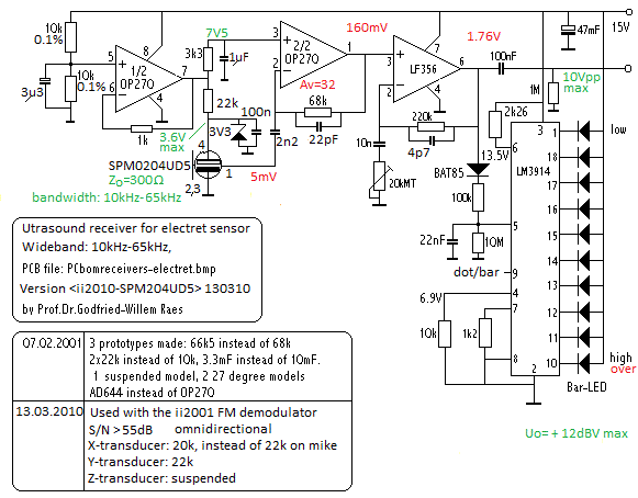
The sensor of choice used in our design, the SPM0204UD5 is an SMD MEMS component produced by Knowles Acoustics. Essential parameters and values are given in the circuit drawing. Note that the dot-driver is not a VU-meter but a tool to be used for alignment. It reflects signal strength of the carrier wave. Reception will be best when any of the center LED's are turned on. When the red LED's turn on, the preamp is saturated and the signal clipped.
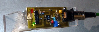
The X and Y receivers, fitted into their half opened housing,
look like: 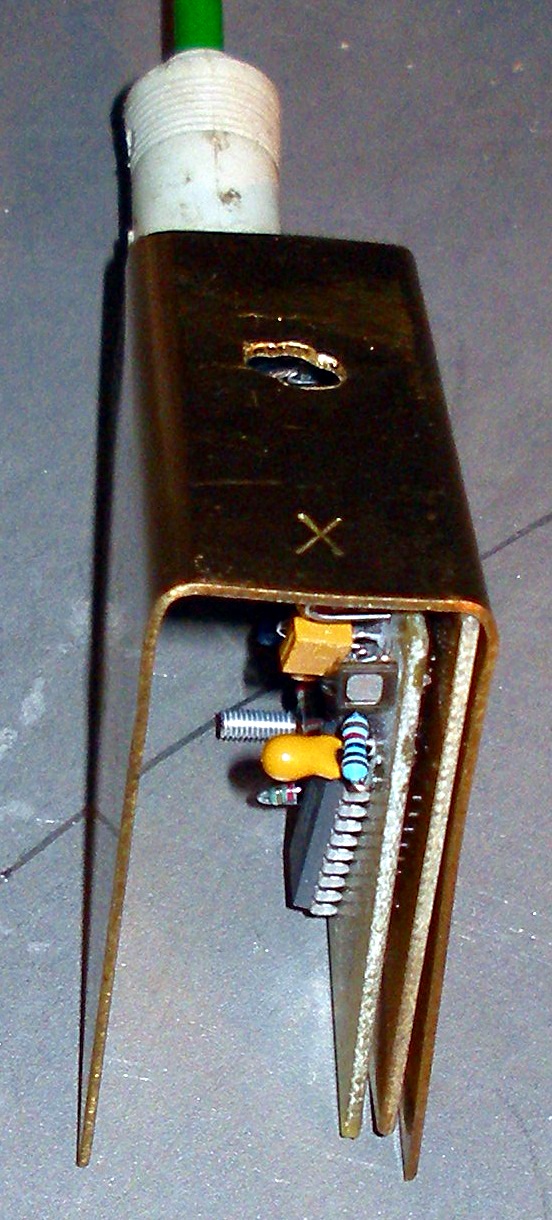 Shielding of the circuit, although not shown in the picture, is very important,
since the circuit is very sensitive to electromagnetic disturbances in its neighborhood
as commonly encountered with the proliferation of switch mode power supplies
and motor controllers.
Shielding of the circuit, although not shown in the picture, is very important,
since the circuit is very sensitive to electromagnetic disturbances in its neighborhood
as commonly encountered with the proliferation of switch mode power supplies
and motor controllers.
Analog processor board:
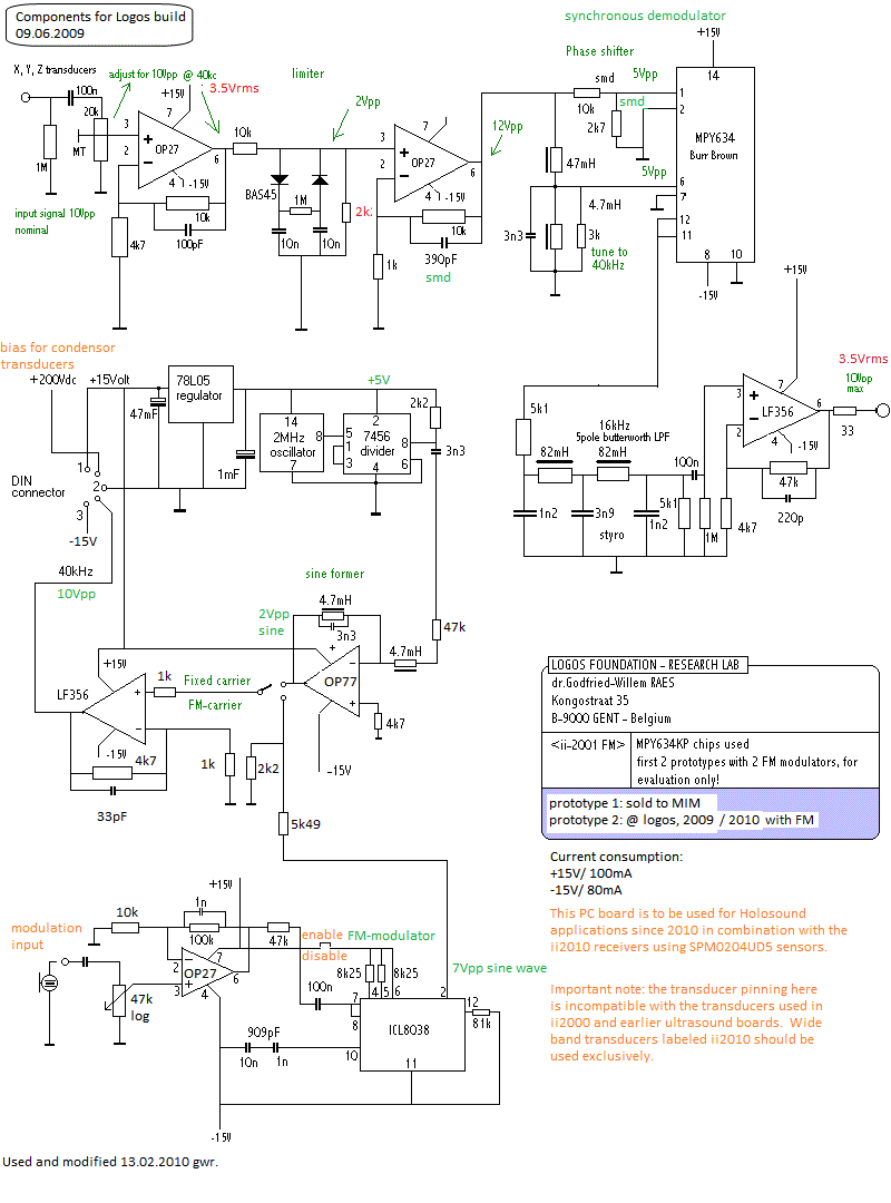
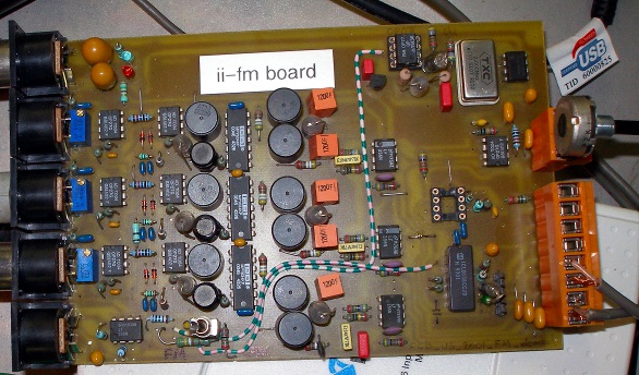
The outputs of this analog computer can be sampled by normal audio cards. For full 3D gesture rendering, 3 channels of audio are required. To allow calculation of distances -requiring FM modulation of the carrier- one should use the fourth analog channel to sample the modulation signal. (5) The circuit, three channels according to the circuit above, fits nicely on a Eurocard board (100x160 mm) and looks like:
The limiter circuit with the two back to back diodes, is an old classic that will look familiar to those who ever worked with short wave radio circuitry. It's a very nonlinear circuit giving good overload protection on large spikes and overloads. We provided it for we wanted to use the circuit in combination with arbitrary sound sources extending in the ultrasonic range: bats, small bells, key-rattle, breaking glass, gas leaks etc... In a measurement system, this part of the circuit is inappropriate. It distorts amplitude measurement and thus body surface estimation. But, if signal levels are kept below the forward voltage of the diodes, the circuit can very well be used for reliable amplitude calculations. To make the adjustment of the input levels easier, we made a small analog read out as follows:
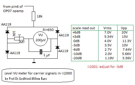 Three
of these circuits are required and placed in top of the analog computing board.
(12)
Three
of these circuits are required and placed in top of the analog computing board.
(12)
The demodulation takes place in a synchronous multiplier circuit. The advantage is that it makes an intrinsic high pass filter canceling out most extremely slow and involuntary movement related doppler frequencies. In the circuit used for <ii2000>, we demodulate against an ultra stable carrier frequency reference and had to cope with very large slowly moving DC offsets that had to be removed in the processing software. The synchronous demodulator has a fixed phase angle relation between both of its inputs. Even sharper synchronous carrier separation can be obtained using 40 kHz crystals instead of the resonant LC circuit used here. We did not use crystals in this design however, because of the trouble we had with loss of carrier signal in frequency modulation schemes, required for distance estimation.
A deficiency of the presented circuit is that the demodulation frequency is not easily tunable and with given component values, centers around 40 kHz, the most commonly used frequency in ultrasonic applications. It would be a benefit to be able to tune to arbitrary carrier frequencies in the range 20 kHz to 200 kHz.
An easy way to make the demodulation frequency independent is to feed to multipliers with the signals of a pair of transducers, so xy, yx and zx. The output signals will now be the product of both inputs, and although the demodulated signals reflect the gesture very well, the math involved to bring the data back to real world units (body surface and movement speed) becomes very complicated. (Raes, 1993) A proposal -using pure analog circuitry- to solve this problem is given in this block diagram:
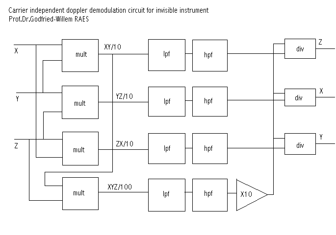
The multipliers can be either AD633 type (low cost. Analog Devices), or MPY632, AD534 etc (expensive but a lot more precize). The dividers can be realized using the same chips in the appropriate divider configuration.
This idea can be applied also on individual receiver circuits as we found out. In order to achieve this, each receiver is equiped with two sensors placed closely together. After preamplication, both signals are multiplied in an analog multiplier, functioning here as a phase comparator. A 5th order low pass follows and some further amplification in order to get a sufficient signal level for sampling. This is the circuit as we tested it out:
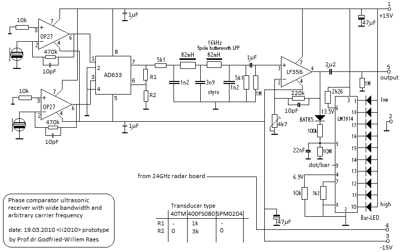
Performance of the circuit as a gesture capturing device is good, but with the given components, the noise level (S/N ratio worst case, using 40TM transducers, 42 dB) is inferiour to previous designs. This is mainly due to the 1 mV noise found on the output of the (cheap) multiplier. Another issue with this circuit is that it is very sensitive to large DC offset variations on the multiplier output in reaction to amplitude changes of the input signal. This could only be remedied by applying a phase shifter between both inputs as suggested in the application notes for the multiplier chip by Analog Devices. Unfortunately, phase shifters work only well if the carrier frequency is constant and thus that sollution would rule out the neat feature of this circuit, its carrier frequency indepency. However, a phase shifter can also be realised mechanically:
When we consider only the sinusoidal ultrasonic carrier signal component, leaving the doppler shifted components out of consideration, the multiplier operates as a squarer and thus, in the frequency domain, as a frequency doubler since we then have
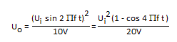
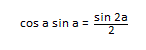
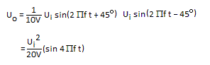
This transfer equation shows a very high DC offset depending on input amplitude. To get rid of this, we can create a phase shift between the X and Y inputs of 90 degrees, and applying the textbook equation,
we can obtain:
Since both inputs in our application use individual sensors,
it becomes possible to realize the phase shift without appeal to electronic
networks. It is sufficient to place one of the transducers a quart wavelength
further back from the other. For a 40 kHz carrier, this means 2.125 mm, since
a full wavelength corresponds to 8.5 mm.
A side remark: the circuit works very well for bat detection without any need
for tuning, if used with the SPM0204 transducers.. If the output is to be sampled
and the sampling rate in use is lower than 32kS/s, an extra lowpass filter on
the output becomes mandatory.
Although not discussed in full depth in this note (9), we have
been using this board in combination with our 24 GHz microwave radar doppler
receivers. The radar board is mounted piggy-pack on the ultrasound receiver
board with the sensor alligned with the ultrasound sensors. This combined sensor
offers the possibility to derive the absolute distance to the moving bodypart,
by measuring the time difference between both demodulated doppler signals. Since
ultrasound travels at the velocity of sound (340 m/s) and radar at the velocity
of light, the time between reception of both signals allows us to derive distance:
s = 340.t Of course the resolution will be a function of sampling rate. If the
sampling rate is the common 44.1 kS/s, resolution will be 7.6 mm. Here is the
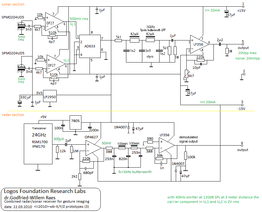
full circuit for the combined sensor as we made it:
The principle behind the distance measurement technique made possible by this circuit is shown in the graph below, showing the signals for a single small gesture:
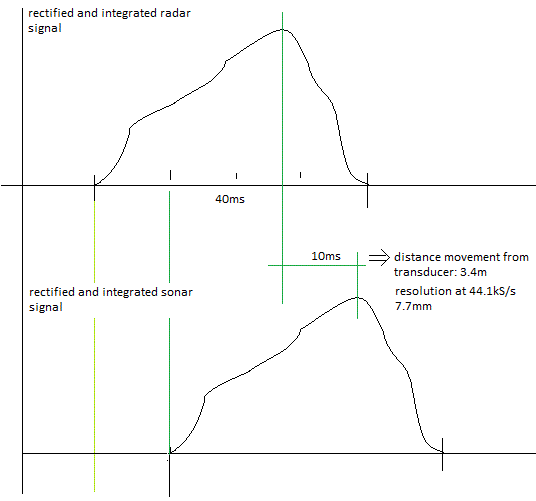
It is generaly not possible to reliably find the start of the gesture signal and hence we better look for a local maximum in the data. Of course latency is introduced this way. Correlation of both waveforms is a better alternative, in the sense that it gives more reliable distance data, but it is more math intensive and may lead to even more latency. For non real-time applications this is obviously not an issue.
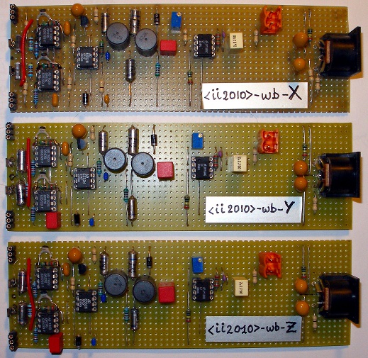
This circuit was build in 3 copies to serve as X, Y and X receivers. The breadboarded circuits for the upper part (sonar) came out to look like:
The signal noise ratio measured with this circuit -properly enclosed- attained 60dB, Further improvements are still conceivable and possible: by using B&K ultrasonic measurement microphones in combination with the best available multipliers on the market and by nulling out all offset errors, an improvement with ca. 12dB can be anticipated. The price however, would also rise with some 40dB... The S/N ratio obtained with the radar section is at least 20dB worse than that of the sonar section. Hence, data analysis should be based on the sonar signal leaving the radar signal for redundancy checks and distance determination only. Spectrum measurements with this system, operated with a 40kHz carrier, revealed that for normal human gestures, no gesture related frequency components higher than 4kHz are traceable in the sonar signal. A low pass filter with a cut off at 4kHz would have been enough, but can be implemented in software quite easily if the sampling rate is high enough. (11)
In order to test this hardware gesture recognition platform with both sonar and radar sensors, we made a board to make interfacing to a computer based audio input device (6 channels of audio line level input are required for a complete 3-D gesture rendering) an easy matter. The circuit looks like:
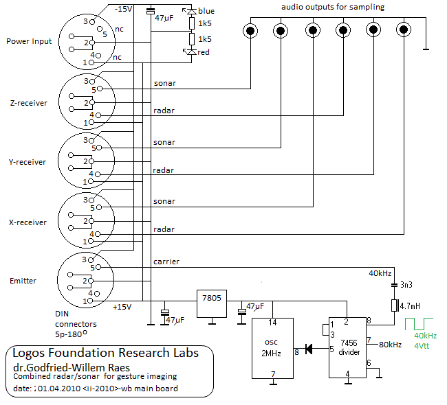
The 7456 divider chip used here is an obsolete TTL part produced by Texas Instruments, no longer in production. Since we had still a good quantity in stock, we used it nevertheless. Software for gesture control of the robot orchestra, using this hardware platform is developed by Kristof Lauwers at the Logos Foundation using PD. Sample code is available on request.
The test board looks like:
Emitter board:
This small board receives the carrier signal -either fixed frequency or an FM modulated signal- from the analog computer board described above. The design goal was to achieve a sound pressure level of ca. 120 dB (measured at 1 m distance) with wide area coverage. (7) Basically the circuit is a bridge amplifier delivering an output voltage swing almost twice as large as the power supply voltage. The LF356 was selected for its excellent behavior in driving capacitive loads.
![]()
The practical realization looks like: ![]()
The input potmeter can be used to adjust the output level such that optimum S/N ratio is achieved. It also allows adjustment to variable distances in the setup. In fact, the placement of the emitter does not have to be strictly on the vertex of the ground plane of the imaginary tetrahedron, but can be placed much farther away. The distance to the X,Y and Z receivers however has to be the same.. Although not drawn in the circuit drawing, our practical realization of the circuit uses an array of four 400ET080 transmitters, connected in parallel and aligned vertically. The beam angle for these transducers is specified as 125 degrees. The vertical stack alignment was done in an attempt to meet the sound pressure levels that we obtained in using the Murata piezoelectric transducers in earlier designs. These 16mm Murata piezoelectric transducers however are quite unidirectional and do not allow frequency modulation due to their inherent sharp resonance at 40 kHz. Sound pressure measurement with this circuit and the 400ET080 transducers revealed that we could not obtain the required 120 dB. Hence we also made a similar circuit, this time using two 10 mm diameter 400ST100 ceramic transducers mounted in a horizontal plane. The modulation bandwidth with these transducers is limited to 2.5 kHz, but 120 dB sound level pressure could be reached. However the voltage over these transducers should be kept below 15 Vrms. The capacitance of the transducers is 1900 pF and the beam angle limited to 72 degrees.
The required sound pressure level could be reached with the circuit below. Here we used an array of four Murata MA40S4S emitters, specified for 120dB SPL at 30cm. The beam angle for each transducer is specified as 80 degrees, thus in order to have a somewhat wider coverage, we arranged the array of four transducers in a square on an imaginary sphere segment. Each transducer has a capacitance of 2.55nF and hence the total capacitance (10.2nF) if we connect them all in parallel, would marginally exceed the capacitive drive specification for the LF356 opamps. We tried this, and in fact observed a very odd phenomenon in that the lower opamp undergoes a complete phase reversal as soon as the input signal exceeds a certain limit, yielding almost no output from the circuit. Hence we used the series/parallel connection as shown in the circuit below. Since we had plenty of headroom -the transducers should not be driven with higher voltages than 20Vpp- we suffered no penalty from this.
![]()
Although we now meet the sound pressure level requirements, this circuit does not lend itself very well for FM-modulation due to the small bandwith of the transducers.
Other experiments carried out have been:
1.- Extended range tweeter loudspeakers: highly inefficient, very bulky and... way too directional. Imagine: we needed a 150 W amplifier to feed a 200 W titanium dome tweeter in order to get 120 dB sound pressure at 40 kHz at 1 meter distance.
2.- Capacitive transducers requiring a DC bias voltage in the order of 300 V. Their principle of operation is identical to that of electrostatic loudspeakers. These work pretty well and they are indeed suitable for FM applications, but due to their large diaphragms, they are also way too directional (12 degrees) for our application here. The type we tested is 500ES430, although specified for 50 kHz, they also operate well at 40 kHz. A particular problem is raised by the required +300 V bias: if this voltage is applied through the 5 conductor cable, the latter becomes highly microphonic itself. Generating this voltage with a small switcher on board at the other hand, causes lots of interference with the ultrasound carrier. A more clever circuit, wherein the DC voltage is obtained through diode multiplication starting from the carrier signal itself, should be designed.
3.- Plasma ion sources are on the design table a perfect match:
They are by nature omnidirectional and can easily cope with FM. However, they
are highly sensitive to air flow -they sputter- and they cause extreme EMC in
the environment. The fact that they are intrinsically dangerous as they operate
with 20 kV voltage levels, also limits their usability. (6)
The ideal transmitter has not been found sofar. The importance of the search
for very powerfull transmitters lies in the simple fact that the signal to noise
ratio at the receivers end, tracks perfectly with the sound pressure level of
the transmitters. Research goes on.
A final note on interference.
In general sonar technology is by far less sensitive to environmental interference, although care must be paid to avoidance of turbulencies and windflow as well as of temperature gradients. However, another source of interference is formed by the extended spectral contents of quite some sounds of real musical instruments. This interference does not occur with loudspeaker generated environmental music, since audio systems filter out by their very nature all frequency components above 20 kHz. Since we are using this technology in the implementations of our invisible instrument to control our robot orchestra, composed of purely acoustical sound sources, we often noticed disturbances with certain loud sounds such as originating from our robot saxophone <Autosax>, struck metal shells in <Llor> and edge whistle tones generated by organ pipes in our <Qt>, <Bourdonola> and <Piperola> robot. The problem can be avoided only by placing the sensor system far enough from the acoustical sound sources. Unfortunately, in our premisses at the Logos Foundation this is impossible because of lack of space...
Dr. Godfried-Willem Raes
Notes:
(1) This project is part of the ongoing research of the author in gesture controlled devices over the last 35 years. Earlier systems, based on Sonar, Radar, infrared pyrodetection and other technologies are fully described in "Gesture controlled virtual musical instrument" (1999) as well as in his doctoral dissertation 'An Invisible Instrument' (1993). Artistic productions and compositions using these interfaces and devices have been: <Standing Waves>, <Holosound>, <A Book of Moves>, <Virtual Jews Harp>, <Songbook>, <Slow Sham Rising>, <Gestrobo>, <Quadrada>, <Technofaustus> , <Butoh>, <Ices>, <Bodies of revolution>, <Differentials> etc.
(2) As of august 16th 2009 the world record for running in the 100 m competition is fixed at 9.58 s. This corresponds to a movement speed of 10.52 m/s or 37.8 km/h. Needless to say that such speeds are not encountered amongst 'normal' people, even not when they get involved in the wildest forms of dancing.
fd = 2 v fo cos(a) / c
(3) Here is the circuit as we developed it for the Monacor electret MCE2500 microphone:
This circuit has very good wide band characteristics but suffers from a poorer signal noise ratio.
(4) Here is the circuit as we developed and tested it with the Prowave 400FS060 sensor:
(5) for a more in depth treatment of FM modulation for distance determination see: RAES, Godfried-Willem "Microwave Gesture Sensing" (Ghent, 2009)
(6) See our design for a real digital loudspeaker: Talking Flames. Since the sound source here is a virtual point, the radiation pattern is inherently spherical.
(7) Most data sheets for ultrasound transmitters specify the SPL measured at a distance of only 30 cm, whereas the standard for acoustic measuments specifies it at a distance of 1 m. This means that we have to subtract ca. 12 dB to bring the data back to common standards. Also note that in our setup, the distance between emitter and receiver is normally 3 m. This entails that the SPL at the point of the receiver will be 20 dB down as compared to the SPL as given in the data sheets.
(8) Transducer data comparisson table:
| Brand | Type | technology | frequency fc | sensitivity (receiving) | SPL (output) | beam angle | bandwidth | S/N | diameter |
| Murata | MA40S4R | piezo | 40kHz | -63dB | - | 80 | 9.9mm | ||
| Murata | MA40S4S | piezo | 40kHz | - | 120dB(@30cm) | 80 | 9.9mm | ||
| ProWave | 400FS080 | PVDF film | 40kHz | 95dB (@10cm) | 360/80 | 4kHz | |||
| ProWave | 800FS049 | PVDF film | 77kHz | 360/80 | 5mm | ||||
| Knowles | SPM0204UD5 | MEMS | 10-65kHz | -47dB | - | omni (360) | 55kHz | -59dB | 4x5mm |
| ProWave | 400ET080 | piezo (closed) | 40kHz | - | 100dB(@30cm) | 125 | 1.5kHz | 9.1mm | |
| ProWave | 400ER080 | piezo (closed) | 40kHz | -80dB | 125 | 2 kHz | 9.1mm | ||
| ProWave | 400ST10(0) | piezo | 40kHz | - | 112dB(@30cm) | 72 | 2.5kHz | 9.7mm | |
| ProWave | 400SR10(0) | piezo | 40kHz | -70dB | 72 | 3kHz | 9.7mm | ||
| ProWave | 400ST16(0) | piezo | 40kHz | - | 120dB(@30cm) | 55 | 2 kHz | 16mm | |
| ProWave | 400SR16(0) | piezo | 40kHz | -65dB | 55 | 2.5 kHz | 16mm | ||
| ProWave | 500ES430 | electrostatic | 50kHz | -42dB | 119dB(@50cm) | 12.8 | 43mm | ||
| Monacor | MCE2500 | electret | 20Hz-65kHz | -46dB | - | cardiod | 65kHz | -58dB | 6 mm |
(9) The radar system for gesture measurement is described in more detail in Raes, Godfried-Willem, "Microwave Gesture Sensing"(Ghent, 2009)
(10) The software used for making sense of all the signals described here is treated in the second part of this paper: "Namuda Gesture Recognition"(Ghent, 2010)
(11) The system as described here was used for an exhaustive measurement session lead by dr.Jin Hyun Kim during the second week of may 2010. The sonar receiver signals were recorded as audio tracks simultaneous with the audio of the M&M robotorchestra playing under the control of our own Namuda gesture recognition software refered to in the previous note. At the same time, a high speed video recording (300fps) of all gesture input was made, thus providing a very wide data set for further analysis and research. A paper presenting the results of this investigation will we published in due time.
(12) A word of warning with regard to the meassurement of the signal voltage levels may be appriate here: if using a multimeter with a true RMS scale, check the characteristisc of the meter beforehand. The large majority of such instruments cannot handle AC signals with frequencies up to and above 40 kHz. Even good and expensive ones, such as the Agilent U1252A, is only reliable up to 30 kHz. The Fluke 87 performs well in this repect. The instrument of choice for voltage measurement therefore remains the oscilloscope, though is is a bit clumsy to take on the road...
Bibliographical references:
First published on the web: 16.03.2010 by dr.Godfried-Willem Raes
Last update:2010-05-26