
 Springers
automated percussion
archive file describing version 1.0 (2000)
click here for the latest version
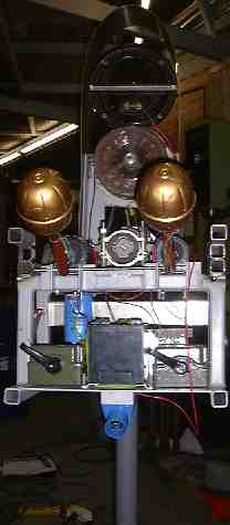
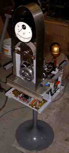 The central part
of this computer controlled musical automat is a robust free standing
module containing all the control electronics, the power supply and three
automated instruments: 2 shakers (maracas) and one large siren. The design
of this module resembles an altar piece, maintaining strict symmetry.
The central part is formed by the motorized and belt driven siren. In
top, a large voltmeter reflecting the electrical state of the instrument.
Voltmeter and siren are covered with an arc made of stainless steel.On
the backside of the voltmeter, a rotating flashing light is mounted. From
the underside of the instrument we see a row of four XLR-LNE (HV) connectors.
Here the wires feeding the <Springers> originate. These <Springers>
are a computer controlled assembly of four free standing percussive instruments
using very large springs. All spring sound sources incorporated in the
<Springer>-instruments are highly reverberating and can be placed,
far away from the controll unit, freely in a large space.
The central part
of this computer controlled musical automat is a robust free standing
module containing all the control electronics, the power supply and three
automated instruments: 2 shakers (maracas) and one large siren. The design
of this module resembles an altar piece, maintaining strict symmetry.
The central part is formed by the motorized and belt driven siren. In
top, a large voltmeter reflecting the electrical state of the instrument.
Voltmeter and siren are covered with an arc made of stainless steel.On
the backside of the voltmeter, a rotating flashing light is mounted. From
the underside of the instrument we see a row of four XLR-LNE (HV) connectors.
Here the wires feeding the <Springers> originate. These <Springers>
are a computer controlled assembly of four free standing percussive instruments
using very large springs. All spring sound sources incorporated in the
<Springer>-instruments are highly reverberating and can be placed,
far away from the controll unit, freely in a large space.
 The instrument
can be played by standard MIDI commands, using our GMT software but is
also capable of listening to pure algorithmic commands.
The instrument
can be played by standard MIDI commands, using our GMT software but is
also capable of listening to pure algorithmic commands.
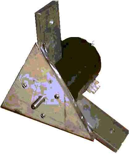
The picture to the right is a detail of the top part of the tetrahedral structures from where the springs are suspended. The large cilindrical object is the hefty solenoid activating the springs.
Four of these components form the top vertexes of four tetrahedral structures with legs ranging in lengths as shown and choosen from the table below:
| Leg length | h min. (at 60 degrees, tetrahedron) | spring length including eyelets. | barrel resonator heigth | springrate |
| 6000 mm | 4896 mm | 4010 mm | 886 mm | 1.8 N/mm |
| 4920 mm | 4015 mm | 3434 mm | 580 mm | 1.8 N/mm |
| 4080 mm | 3329 mm | 3029 mm | 300 mm | 1.8 N/mm |
| 3360 mm | 2742 mm | 2522 mm | 220 mm | 1.8 N/mm |
| 2820mm | 2301 mm | 1750 mm | 500 mm | 1.8 N/mm |
| 2340mm | 1909mm | 1550 mm | 400 mm | 1.8 N/mm |
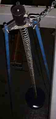 The springs are
attached to large empty oil barrels (200 liter, for the largest selection
of leg lengths, for the smallest selection, 100 liter) serving as amplifiers.
In one case, we constructed a resonator from an old circus bass drum,
by providing it with a single brass membrane to which the spring as attached.
The legs are made of 3/4" gas tubing, reinforced at the slotted ends.
The springs are
attached to large empty oil barrels (200 liter, for the largest selection
of leg lengths, for the smallest selection, 100 liter) serving as amplifiers.
In one case, we constructed a resonator from an old circus bass drum,
by providing it with a single brass membrane to which the spring as attached.
The legs are made of 3/4" gas tubing, reinforced at the slotted ends.
The instruments are made and designed to be a part of the <Slag-Werk> project realized for 'Web Strikes Back' at the occasion of the Tromp biannual, october 2000 in Eindhoven, the Netherlands.
The <Springers> use dedicated hardware, designed for musical automats such as player pianos, percussion instruments, organs and even bowed instruments. Details can be found in our course on experimental music on this same website.
The hardware in the control module consists of following printed circuit boards:
1. a parallel bus-board, designed for many of our automated instruments. (cfr. Klung, Player Piano, Harma, Troms, ThunderWood, Dripper, Rotomoton, Gorgel...) This board gets its input from a parallel printer port from a stardard wintel PC running Window98 with MMX command set and multimedia timer features. However, it is also possible to use any other microprocessor or controller as long as it can implement centronics like outputs. Thus using ActiveWire USB devices, even USB can be used as an interface to <Springers>. The pc board for this circuit contains the 5V regulator used for the digital signal sections on the other boards as well. The circuit, a demultiplexer, looks like:
 The second port marked reserved in the schematic, is used to steer
the PWM board for the siren. This circuit is documented further. This
way data for the siren cannot accidentally interfere with note data. The
second 'reserved' port (ExpPort2) is used to drive the rotating flashlight.
Here again a simplified DAC/PWM circuit is used. Other than shown in the
schematic, the latch used for both Note-port (used for the siren control)
and ExpPort2 are specified as 74HCT573: these are transparant latches
making continous data transfer possible when the strobe is kept low.
The second port marked reserved in the schematic, is used to steer
the PWM board for the siren. This circuit is documented further. This
way data for the siren cannot accidentally interfere with note data. The
second 'reserved' port (ExpPort2) is used to drive the rotating flashlight.
Here again a simplified DAC/PWM circuit is used. Other than shown in the
schematic, the latch used for both Note-port (used for the siren control)
and ExpPort2 are specified as 74HCT573: these are transparant latches
making continous data transfer possible when the strobe is kept low.
2. Note driver board. This pc board houses the power mosfets used to steer the solenoids used for activating the sound sources. [ comment on these circuits, first developed for our player piano and also used in automats such as <Klung>, <Troms>, <Harma>, <ThunderWood> can be found at http://www.logosfoundation.org/logos/kursus/2116.html. ]
3. The power mosfets we used for controlling these solenoids are IRL640 (or the equivalent Harris RFP10N12L), since these switch on TTL levels and are capable of dissipating 60Watts. The current rating is 10A and their Uds limit is 120V. The rather high gate capacitance (850pF) is not a real problem since switching speeds in this application are inherently pretty slow. For this reason we did not fit a resistor between gate and ground in the driver circuit. Note that when the power suppy is switched on, all latches will go to a high state, thus sounding all springers at the same time. To avoid this, users should always first switch on the 5V power supply and only when the controlling computer is up and running, switch on the 60V power supply for the solenoids. Hence the dual switch in the power supply.
4. The power supply for this instrument is rated for 350Watts. It consists of different sections:
- a.- high power section for the solenoids as well as the siren: 60V / 250W
- b.- logic power section: 5V / 1A
- c.- analog power section: +15/-15V - 250mA
- d.- high power section for the rotating flashlight: 24V / 100VA.
Solenoids:
For the <Spingers> we used solenoids made by Laukhuff, Weikersheim, type number GL90A/15. Officially these are rated 24V at 1.41A. At these conditions, they deliver a power of 55N. Anchor displacement is 25mm and cannot be modified. We took the solenoids to the lab, and derived following table describing operational conditions relevant to our application:
| maximum duty cycle | 100% | 50% | 25% | 10% |
| Power (at 20 celsius) | 34W | 76W | 135W | 300W |
| Voltage | 24V | 36V | 48V | 72V |
| Maximum ON-time | no limit | 360" | 36" | 3" |
 The
springers are connected to the control module with long cables ending
in Neutrik power connectors. The pinning is shown in the drawing. The
female connectors are situated on the underside of the control module.
Activation repetition rate is limited by the solenoids in combination
with the spring-loads. Maximum pulsing frequency is about 65Hz.
The
springers are connected to the control module with long cables ending
in Neutrik power connectors. The pinning is shown in the drawing. The
female connectors are situated on the underside of the control module.
Activation repetition rate is limited by the solenoids in combination
with the spring-loads. Maximum pulsing frequency is about 65Hz.
The <Shakers> use bidirectional solenoids of the same type as we used in <Thunderwood> for the thundersheet as well as for the bamboo windchimes.
The siren is driven by a separate 8 bit port (the port labeled Note-Port in the schematic), via a DAC - PWM modulator, and uses a strong DC motor. This motor drives the siren through belts. The motor belt wheel is 40mm, whereas the siren wheel measures 140mm. For safety reasons we limit the speed of the motor by using 70V dc as maximum voltage. The motor when driven with 210V dc rotates at 7000 rpm. Not only would the siren turn dangerously fast, but also -since sirens have sound output proportional to pitch- it would become largely over 120dB in loudness at an earpiercing pitch...
We designed a digital to PWM circuit for this element as follows:
For the rotating flashlight, requiring 24V at 3A for full speed operation, we designed a somewhat simplified but very similar circuit. To save on power supply connections (the DAC0808 requires split supply), we used a less precize R2R network directly driven from the ExpPort2 8-bit port on our demultiplexer. We use only the 7 highest bits and save the lowest bit for a special purpose: this bit on start up will be high, thus inhibiting the flashlight. To operate the flashlight, your software should always reset bit 0 on the corresponding port.
 Obviously,
writing a zero byte to the port, will also switch off the flashlight.
Obviously,
writing a zero byte to the port, will also switch off the flashlight.
Note that we used a 3140 opamp in this circuit. It's a mosfet type that can drive the output all the way to ground even with a single power supply. Do not subsitute this opamp for a CA3130, since this type is limited in its power supply voltage to only 16V.
Although the circuit as given is far less precize than the previous one and also suffers a lot from glitches on the datalines, its perfectly well suited for this type of anyway very slow reacting load.
To power this part of the engine, we used 2 Erea12V transformers as used for Halogen 12V lighting. We placed them in series and rectified the output. We first tried their electronic equivalents, but had to remove them again: the outputs of these (cheap) devices are extremely dirty and can have spikes larger then 100Volts. They do not work well when used for powering PWM circuits. Vicor SMPS power modules would have been a good alternative, but we did'nt have any at hand...
 Music:
If you are using <GMT> under Power Basic, you can use all specific hardware control functions and procedures provided in our DLL library. A midi command converter was written in <GMT> by Kristof Lauwers. This is now a standard part of the GMT DLL libraries.
Midi mapping:
- Largest springer: note 120
- Second largest springer: note 121
- Third largest springer: note 122
- Smallest springer: note 123
- Shaker 1 : notes 124-125 (alternating)
- Shaker 2: notes 126-127 (alternating)
- Siren: note 1, velo: 0-127, connected to DAC port.
- Rotating flashlight: note 2, velo 0-126, connected to 2nd DAC port.
- For those who want to see this rather on a musical staff:
Concerts where <Springers> could be heard:
- Tuesday 17th of october 2000: Logos Tetrahedron: Try out concert
- Tuesday 24th to Sunday 29th of october 2000, Eindhoven, TU: <Web Strikes Back Project>
- Thursday august 2nd 2001, Ghent: Logos Tetrahedron
- Sunday september 9th, Sint Truiden, Flam Ijzergieterij (10u00-18u00)
- M&M concerts in 2001 and 2002.
- Thursday november 28th 2002, M&M in Enschede.
- M&M concert on december 19th 2002, Ghent, Logos tetrahedron.
- M&M concert on january 15th 2003, Ghent, Logos Tetrahedron
- M&M concerts (monthly) from january 2004 on.
Mechanics:
The sketch shows the way the shaker solenoids are connected to the shakers. Underneed is the axis of rotation (8mm). Ca. 30mm above this point another pivoting point forms the actioning point . The last pivoting point is drilled lateraly through the anchor of the solenoid. The picture shows the final realization.
Construction collaborators:
- Filip Switters
- Kristof Lauwers
- Moniek Darge
- Kurd Vandevelde
Dimensions:
- Control module:
- heigth: 1650mm
- depth & width: 450mm
- circular base: 500mm diameter
- weigth: ca. 65kg
- Power consumption: 280Watts / 230V AC
- data input: centronics parallel port from Wintel PC
- Springers:
- width: 1600 mm to 6200mm
- height: 5000mm (cfr. table)
- depth: 1600mm to 6200mm
- weigth: 60kg to 100kg each
Insurance value: 5.000 Euro.
Note for organizers: these instruments are very high and cannot be taken into parts. Make sure the space you provide allows for the height of this instrument. Also access routes to the space have to be carefully checked beforehand. <Springers> are collapsable and can easily be positioned and repositioned. This project is suitable for open air performance, since we can put small umbrellas over the top ends of the tetrahedrons. However, this project cannot be battery operated, so mains voltage is required. For transportation, a truck capable of taking a load of 6m20 in length, is required.
The <Springers> automat can be heard on the Logos Public Domain CD <Automaton> (LPD007). as well as on LPD CD <Robodies> (LPD014)
| Back to Web Strikes Back | Back to logos' main index page | To homepage Godfried-Willem Raes |
Maintenance and repair logbook:
01-09.2000: First version of <Springers>, made for the Tromp competition in Eindhoven, Netherlands.
28-08.2006: Start revision of <Springers> for direct midi operation. We can use a single PIC controller. This file is no longer updated and describes only the original version.
Last update:06-08-29