<Rumo>
an automated noise maker
Godfried-Willem RAES
2014 - 2024
![]()
|
|
|
<Rumo>
|
<Rumo>
This robot was named after Luigi Russolo, the most wellknown musician-member
of the Italian futurist movement at the start of the 20th century. Just like
in his pretty primitive and purely mechanical constructions - intonarumori-
, we make extensive use of acoustical amplifiers in this design. So, in a way,
building further on principles highly developed during the period mechanical
roll players and grammophones were developed. The sound sources used here are
mainly springs, steel ribbons, rattles and shakers, membranes, cavity resonators
and rubbed strings.
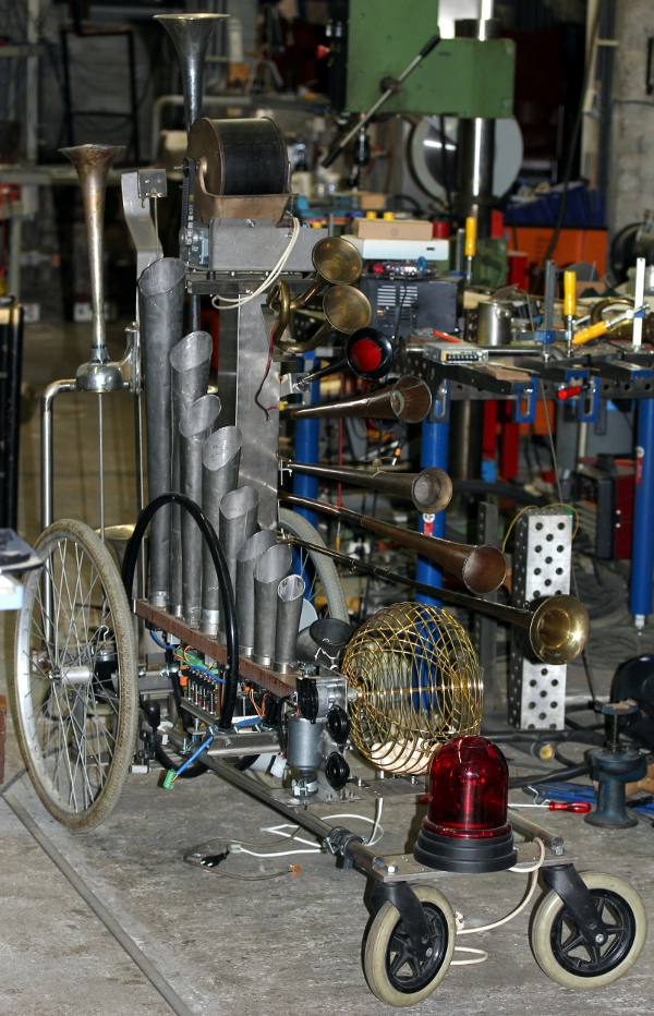
It consists of a variety of very different largely non-pitched noise sources. Here is a one by one overview:
1.-Excited spring with acoustic amplifier: This component uses a very long
spring held between the anchor of an electromagnet at one side, and the membrane
of an acoustic compressor at the other side. The acoustic compressor is coupled
to a conical horn, in fact taken from an old bugle. The resonant frequency of
the horn corresponds to midi note 56.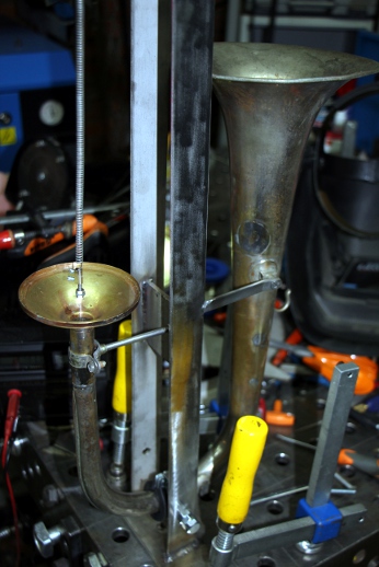 The required voltage is 24V (460mA) but they start working at 12 V.
2. A second second sound source with similar excitation and membrane. For this
one we modified a compressed air horn.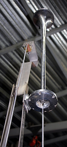 This assembly uses the same type of magnet as the one above.
3. The third sound source is again a spring, but this time coupled to a brass
membrane on a modified ships horn. The electromagnet used here is taken from
a door closing mechanism.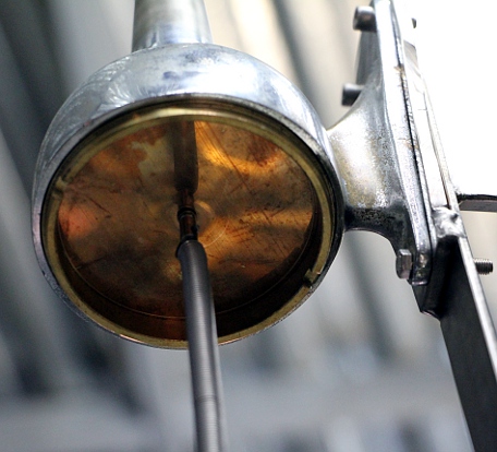
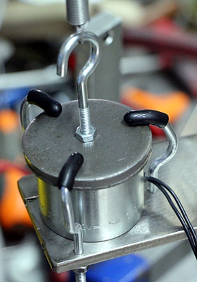 This round Gobin electromagnet
starts reacting at 7 V, but the nominal voltage is 24 V, where it draws 700
mA.
This round Gobin electromagnet
starts reacting at 7 V, but the nominal voltage is 24 V, where it draws 700
mA.
4. A fourth horn, a linear cone in brass taken from an antique hooter, uses
a smaller brass membrane to which a thin curtain spring is attached, rubbed
with a motor driver wheel. The motor is a 24V DC geared motor made by Philips: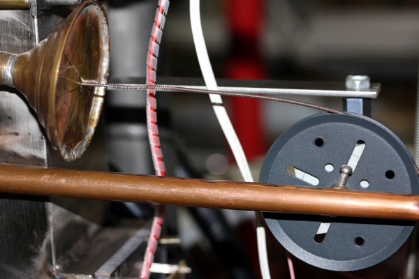
5. A smal electromotor driven compressor for a realistic motor sound: 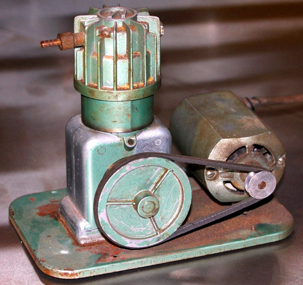 This
compressor also can provide air for a shipshorn:
This
compressor also can provide air for a shipshorn: 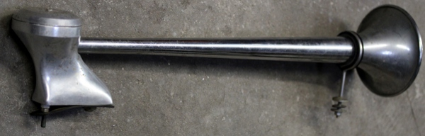
6. Whisper components, using cavity resonators and individual fans. 8 elements.
The control board uses four Microchip 8-bit processors.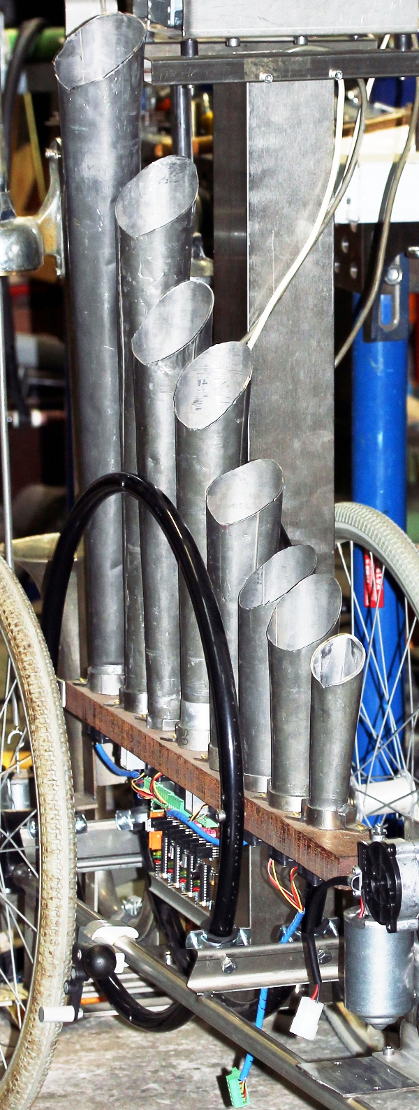 It
is a much improved version of the <Whisper> robot made much earlier. This
version uses PWM-programmable fans.
It
is a much improved version of the <Whisper> robot made much earlier. This
version uses PWM-programmable fans.
7. Small shakers, controlled by the fourth whisper-board processor.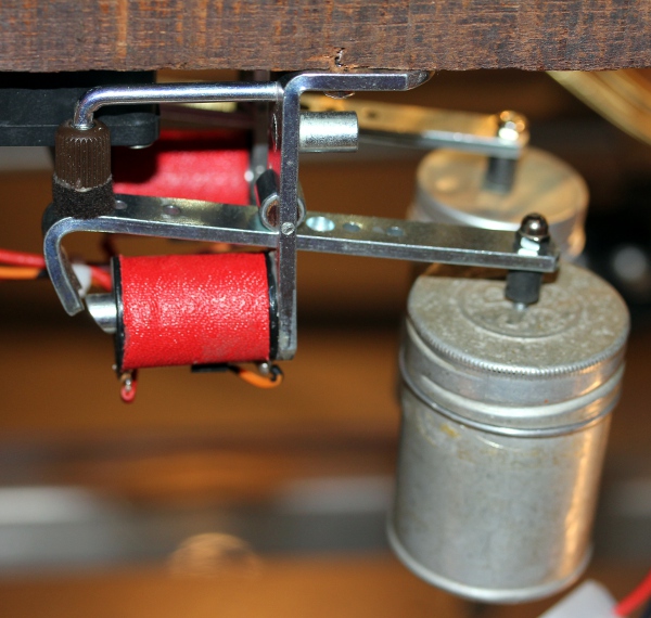 These two small solenoid driven shakers are driven by two modified 12 V Laukhuff
pallet valves. A somewhat larger shaker is driven by the claxon board and a
larger and modified Laukhuff trakturmagnet:
These two small solenoid driven shakers are driven by two modified 12 V Laukhuff
pallet valves. A somewhat larger shaker is driven by the claxon board and a
larger and modified Laukhuff trakturmagnet: 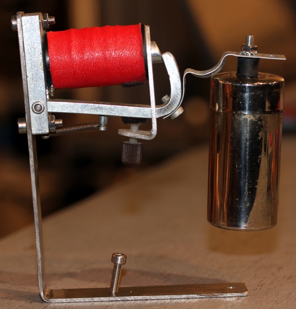
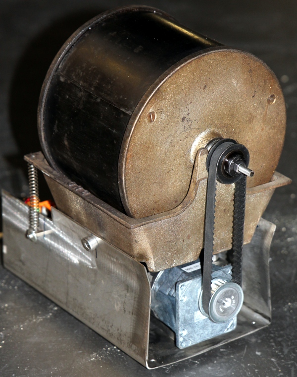
8. A Nestor Martin coffee burner modified to make a rotary shaker.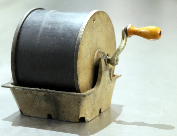 The
handcrank was replaced with a DC motor and a dented driving belt:
The
handcrank was replaced with a DC motor and a dented driving belt: 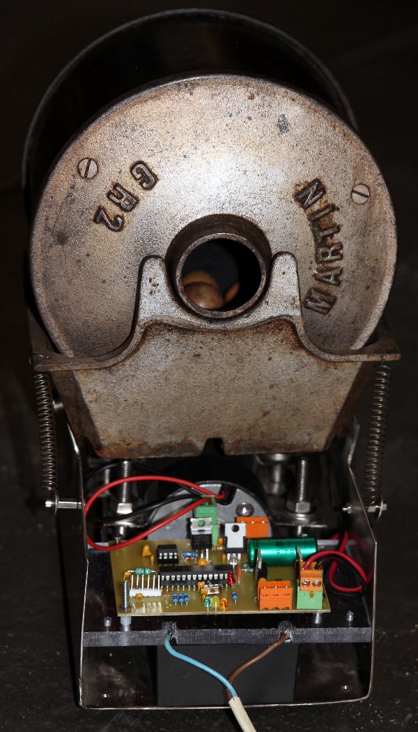
 The drum can be freely
filled with different materials: wooden balls, beans, rice, corn, stones, glass
pearls... each material giving a different sound.
The drum can be freely
filled with different materials: wooden balls, beans, rice, corn, stones, glass
pearls... each material giving a different sound.
9. An industrial claxon horn. (24V - 800mA) sounding midi note 37/42. (C#,
F#)). VEB Funkmechanik Zwenkau DDR, Type SHS57G.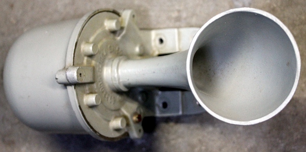 With voltages ranging from 10V to 28V, a pitch variation is reached from midi
note 39 to 43.
With voltages ranging from 10V to 28V, a pitch variation is reached from midi
note 39 to 43.
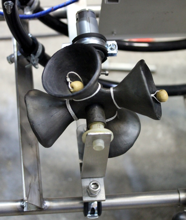
10. Six hooters: Double hooter: 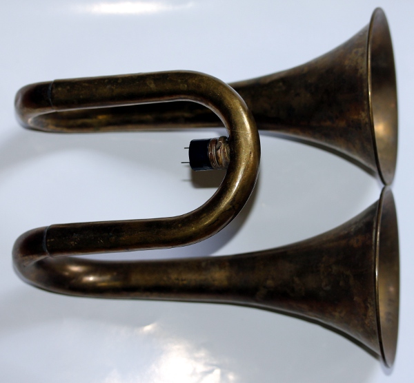 Membrane
driven double hooting horn, resonant frequency midi note 66 (F#, 370 Hz), detail
of the mounting of the small buzzer:
Membrane
driven double hooting horn, resonant frequency midi note 66 (F#, 370 Hz), detail
of the mounting of the small buzzer: 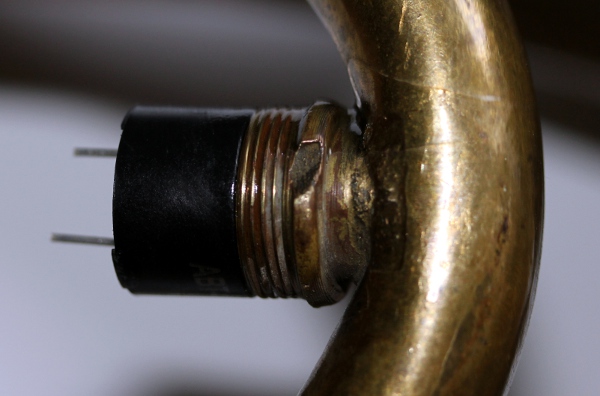 This horn can sound the fundamental F# (66) as well as the overtones 78, 85
and 90. Two more membrane driven horns added using a similar buzzer as a driver.
These are driven by a 16/24-bit 3-channel synth board. An Aida trumpet sounding
Bb added as well as two more large hooters sound D and E. These three are steered
by a separate synth board using IR2104 chips and driving compression drivers.
This horn can sound the fundamental F# (66) as well as the overtones 78, 85
and 90. Two more membrane driven horns added using a similar buzzer as a driver.
These are driven by a 16/24-bit 3-channel synth board. An Aida trumpet sounding
Bb added as well as two more large hooters sound D and E. These three are steered
by a separate synth board using IR2104 chips and driving compression drivers.
11. A large bingo drum, modified and motorised with a geared DC motor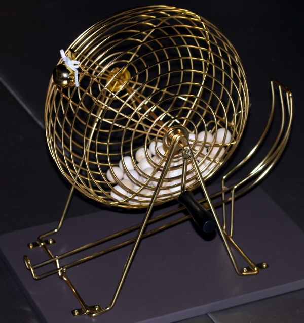
12. Four membrane claxon horns: tuneable in the range 65 to 71. At 12 V these
draw up to 1.3 A.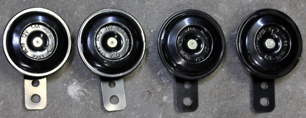 They can perform slight glissandos and start working, more softly at voltage
levels from 4 V on.
They can perform slight glissandos and start working, more softly at voltage
levels from 4 V on.
13. Ritual clay bell rattle driven by a small DC motor.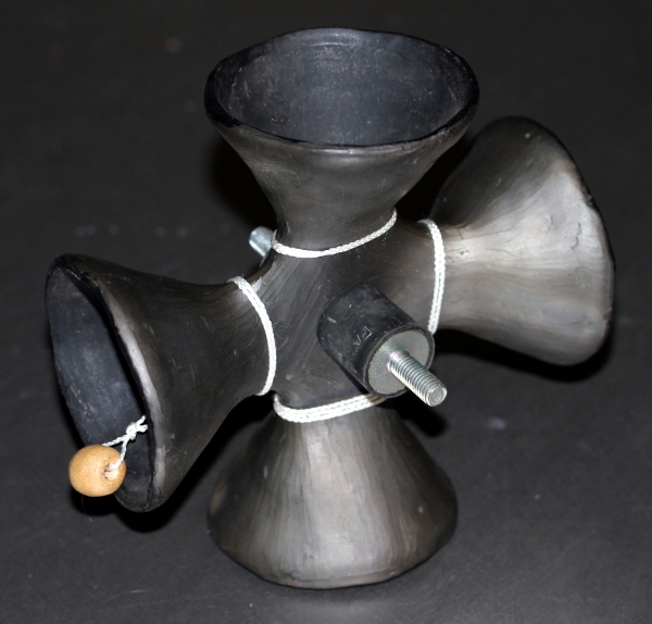 The motor starts running with 1.8 Volts and can get up to 24 V. Nominal voltage
is 15 V,. Current drawn, with the load, at 5 V is 125 mA, at 15 V, 170 mA and
at 24 V rising to 205 mA.
The motor starts running with 1.8 Volts and can get up to 24 V. Nominal voltage
is 15 V,. Current drawn, with the load, at 5 V is 125 mA, at 15 V, 170 mA and
at 24 V rising to 205 mA.
14. Fire alarm bell, sounding note 76, but mapped op note 40 in avoidance of
mapping conflicts with the hooters. 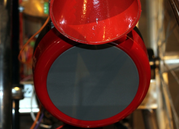
15. A pair of authentic Gnawa clappers made in steel (rusted), driven by two
24 V Emessen pull-type tubular solenoids. These are mapped on the midi notes
41 and 42. In Morocco, they are called Krakeb of karkaba.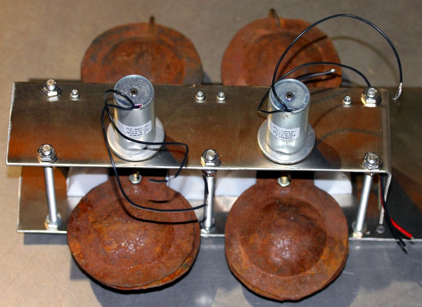
16. A small electromechanical buzzer, coupled to a PVC horn: 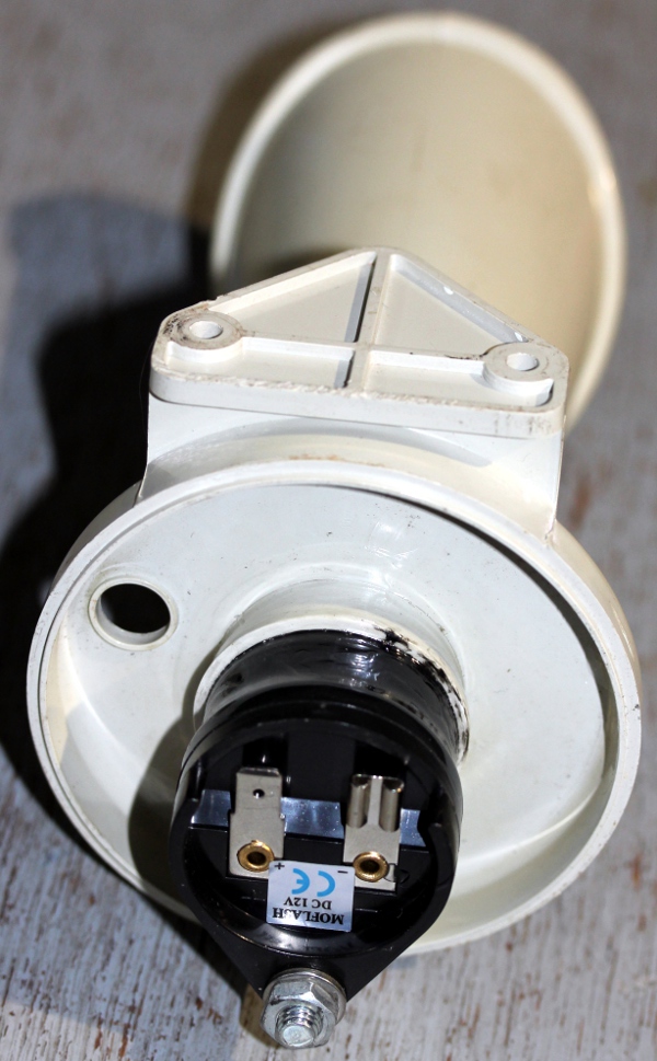 It can perform a small glissando over a range of about a whole tone. So the
real pitch changes between midi note 69 and 71. It is mapped on midi note 47.
It can perform a small glissando over a range of about a whole tone. So the
real pitch changes between midi note 69 and 71. It is mapped on midi note 47.
17. Two motorized 'antique' (newly made in China replica's that is) hooters. Official specifications: 12 V / 3 A, SPL 110dBA, Frequency 490 Hz.
Midi implementation and mapping:
The midi channel <Rumo> listens to is 10. (If counting from 1, this would be channel 11).
the coffee roaster rattle is mapped on midi note 108. The velocity byte steers the speed of rotation of the drum. The ramping on speed changes can be controlled with two continuous controllers 32 and 33. Controller 32 is used to set the ramp-up time for acceleration and controller 33 for the ramp-down time for deceleration.
The bingo cage is mapped on note 107. The velocity byte steers the speed of rotation. For this motor, ramping is not implemented.
The ceramic bell-rattle is mapped on note 105. The velocity byte steers the speed. Ramping is not implemented here.
Lights:
note 120: Tungsten light
note 121: Green LED strip in clay bell assembly.
(velo steers flashing speed)
note 122: relay up lite: Green LED strip.
note 123: relay down lite Green LED strip.
note 124: Red LED strip on Bingo drum and Gnawa
clappers, left (velo steers brightness)
note 125: Red LED strip on Bingo drum and Gnawa clappers, right (velo steers
brightness)
note 126: Red rotating light. ON/OFF only
note 127: Orange rotating light. ON/OFF only
Key pressure is implemented for different notes: for some it can be used to
steer the PWM fed into the device, for others it steers the repetition speed.
Following notes/devices use key pressure to steer repetition speed:
39, 41, 42, 94, 95. Key pressure commands used to steer note repetition are
sticky! If you want the effect turned off, make sure you send the key pressure
command for the note it applies to with value zero.
Following notes use key pressure for PWM resulting in either pitch or amplitude
modulation during the sounding of the note:
33, 34,35,38, 37, 38, 40, 96 to 103
Controllers:
#1: Wind noise in the sound of the hooters
#4: controller 4: amplitude level for the Theban/Aida
trumpet on note 46 (Bb).
#5: controller 5: amplitude level for the note 50 hooter (D)
#6: controller 6: amplitude level for the note 52 hooter (E)
#7: controller 7: volume control - global volume controller
for the hooters sounding B, f# and A.
#12: controller 12: sustain
controller for the hooter on note 46 (Bb)
#13: controller
13: sustain controller for the hooter on note 50(D)
#14: controller 14: sustain
controller for the hooter on note 52(E)
#15: controller 15 - wave-form control for the hooters
sounding B, f# and A.
#16: controller 16 - sustain level controller for the hooters sounding notes
B, f# and A.
#17: controller 17 - attack time controller for hooters
#18: controller 18 - decay time controller for hooters
#19: controller 19 - release time controller for the hooters (release time can
also be controlled with the release byte of a note-0ff command)
# 25: controller 25 - wave-form controll for the hooter sound Bb, Aida trumpet.
# 26: controller 26 - wave-form
controll for the hooter sound D (50)
# 27: controller
27 - wave-form controll for the hooter sound E (52)
#30: controller 30 - sets repetition speed to a common value for the shakers.
#32: ramping up time for the coffee
roaster rattle. Default value = 64.
#33: ramping down time for the coffee roaster rattle. Default value = 64.
#66: Power on / off. This command also resets all controllers to their default
cold-boot values.
#70, #82, #89, #94, #97, #104: pitch bends for the Aida Bb trumpet
#74, #86, #92, #98, #101, #103: pitch bends for the D-hooter. Warning: In many
sequencer programs, controllers 98 and 99 are treated as 'NRPN': non registered
parameter number. Both controllers are then handled together as a 16 bit controller,
where ctrl.99 holds the MSB and 98 the LSB.
#76, #88, #100, #106, #108, #113: pitch bends for the E-hooter
#83, #95, #107, #110: Pitch bend for the note sounding on the B-hooter
#90, #102, #109, #114: Pitch bend for the note sounded by the f# double hooter
#93, #105, #112, #117: pitch bend on the note sounding on the highest A-hooter.
#123: All notes off
Note: the pitch bend controller numbers for the hooters are allways equal
to the midi-note number plus 24.
| subject to minor changes during the ongoing building process |
|
Music composed for <Rumo>:
Godfried-Willem Raes 'Voorlopig Rumoer voor Rumo' (kreatie op 18.05.2023)
Kristof Lauwers 'GF2023 stuk, voor Planeet Jong' (07.2023)
| Back to Logos-Projects page : projects.html | Back to Main Logos page:index.html | To Godfried-Willem Raes personal homepage... | To Instrument catalogue |  |
Construction diary:
12.06.2014: Construction of the first electromagnet assembly. Testing of force
and functionality.
13.06.2014: Construction of the acoustic amplifier with a horn. The membrane
was made from polyacetate
14.06.2014: Welding of a holding construction for the horn and the driver electromagnet.
15.06.2014: Selection of suitable horns for the construction of more acoustic
amplifiers.
16.06.2014: Construction of the membrane for a second acoustic amplifier. Design
of the mounting.
17.06.2014: Discovered another identical electromagnet in our junk-yard. Mounting
flange for the second horn welded. Horn re-assembled with the acoustic amplifier.
20.06.2014: Works on the construction of a thirth membrane amplifier, now using
a thin brass membrane. 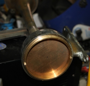
21.06.2014: Sketching of possibilities for an overall shape of the rumo robot.
22.06.2014: Another conical brass part found at the flea market. Useable for
a linear horn and a small membrane. Silver soldering works on the combined structure.
Orifice size for this one is 8 mm. The membrane could be polyacetate, steel
or hard brass.
23.06.2014: Experiments with door closing electromagnets, as these have very
high holding force. DC-Motor experiments for rubbing strings conducted as well.
24.06.2014: Mounting of the third horn assembly on the main structure. Electric
tests: the electromagnet is designed for 12V (5W) at 100% duty cycle.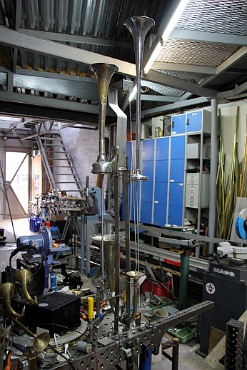
26.06.2014:Some new DC motors ordered from Farnell. Required for the spring
rubbing mechanism. Work for <Rumo> slowed down a bit, as we needed to
be working on <Zi>.
30.06.2014: Start of adding testcode in GMT. Further work on <Rumo> postponed,
as we have to get on with <Zi> first... It looks
like we cannot advance until at least november 2014...
13.09.2015: Time-space in sight to go on with the works on <Rumo>...
15.01.2016: As Logos lost all structural subsidy and thus all governmental support,
further research work on musical robots becomes highly compromised. Corruption
of the members of the advisary commitee that judged the case of the Logos Foundation
was at the base of this tragedy. A feast it was for Blindman, I solisti del
vento, Rosas, Victoria, Piet Van Bockstal, Ictus, Aifoon, Spectra, Hermes, Musica,
Matrix, Recto Verso... and some more reactionary and postmodern organisations.
2017-2019: suffering under complete lack of support. <Rumo> project postponed
without any perspective.
23.05.2020: Start designing a PCB for a version using PWM-controlled fans only.
Instead of replacing almost everything in <Whisper>, we consider to build
a <Whisper-2> robot, maybe as a module of the <Rumo> project.
24.05.2020: PCB designed for the PWM-Fan version. The production of this PCB
was not too succesfull as the film -made with our photocopier- was not black
enough.
25.05.2020: PCB soldered. Some missing components ordered from Farnell.
26.05.2020: Firmware written for the newly made board. Waiting for the missing
components. We cannot test and evaluate without them...
30.05.2020: PCB completed and programmed. First tests with the Sanyo 9GA0412P6G001
fans passed. Regulation is pretty good and seems stable and reliable. It's a
pitty only, we do not have better resolution on the very low side of the PWM
range. At the other hand, this was predictable from studying the air flow curves
in datasheet.
01.06.2020: Construction on the lathe of some more and new cavity resonators.
02.06.2020: Tests and measurements using the Papst 8412N/2GHP 80x80 fan. The
usefull PWM range (using 7-bits in our midi-interface) is 11 to 127. Below 11
the fan does not start running. The
Papst datasheet does not give any information, neither with regard to the
PWM frequency nor the control characteristics.
19.06.2020: Suitable tiger balsem box found on the flea market. Good for another
size whisper unit.
20.06.2020: <Rumo> project taken up again. Considering to integrate it
with the design of a <Whisper 2> robot. PCB's etched for a hub board and
a 12-output pulse-hold board.
21.06.2020: Hub board finished. Start drilling and soldering 12-output pulse/hold
board.
22.06.2020: Soldering 12-output board. Here is a drawing for the placement of
the wire bridges: 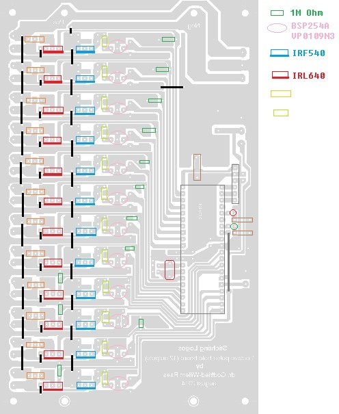 Note that the bridges have to be soldered in place before any other component.
Running into trouble: the P-channel mosfet, type BSP254A, is no longer on the
market. This type was specified for -250V and Rdson = 10 Ohm. A possible replacement
could be VP0109N3-G, but this type is only specified for -90V at 250mA and 6
Ohm. However, the specs are better than the BS250 part we have been using in
late 20th century designs. BS250 had -45V, 180mA and 8 Ohm. Its getter harder
to get discrete parts these days... Running out of IRL640 MOSFET's. New order
placed at Farnell.
Note that the bridges have to be soldered in place before any other component.
Running into trouble: the P-channel mosfet, type BSP254A, is no longer on the
market. This type was specified for -250V and Rdson = 10 Ohm. A possible replacement
could be VP0109N3-G, but this type is only specified for -90V at 250mA and 6
Ohm. However, the specs are better than the BS250 part we have been using in
late 20th century designs. BS250 had -45V, 180mA and 8 Ohm. Its getter harder
to get discrete parts these days... Running out of IRL640 MOSFET's. New order
placed at Farnell.
25.06.2020: A load of fresh IRL640 MOSFETS came in, we soldered them in right
away.
26.06.2020: VP0109N3 P-channel mosfets soldered in, for test and evaluation.
To do this, however, we first should write some firmware...
27.06.2020: Preliminary version of firmware for the 12 output high voltage pulse-hold
board written and tested. This framework is based on the coding for the percussion
components in the <Per> robot.
30.06.2020: Two more whisper components made.
03.07.2020: Recalculation of component values in function of different negative
pulse voltages. This
is derived from the circuit as used for the <Per> robot. For the 10V zenerdiode
we can select either a 1 W type or a 500mW type. In the first case, the zener
current should be 10mA and in the latter case, 5 mA. Thus we can calculate a
small table with values for Rzn for different values of -Vc:
This
is derived from the circuit as used for the <Per> robot. For the 10V zenerdiode
we can select either a 1 W type or a 500mW type. In the first case, the zener
current should be 10mA and in the latter case, 5 mA. Thus we can calculate a
small table with values for Rzn for different values of -Vc:
| -Vc | Rzn 10mA | Rzn 5mA |
| -12V | 700 | 1k4 |
| -15V | 1k | 2k |
| -24V | 1k9 | 3k8 |
| -30V | 2k5 | 5k |
| -35V | 3k | 6k |
| -48V | 4k3 | 8k6 |
| -56V | 5k1 | 10k2 |
| -64V | 5k9 | 11k8 |
| -75V | 7k | 14k |
For more negative values of -Vc, another power Mosfet has to be used instead
of the IRF540 (100V max). Also be carefull not to exceed the 90V limit for the
P-channel mosfet.
07.07.2020: Small diameter tin cans ordered from China, to make whisper mechanisms.
20.07.2020: Tin cans came in from China. Three different sizes, 12 pieces each,
so we can perform experiments with different hole sizes. The cans can also be
used for the construction of small shakers.
27.07.2020: Furher work on the construction of more whisper components.
28.07.2020: Start of the construction of a 'windchest' or wooden mounting plate
for the whisper components.
29.07.2020: Further work on the windchest: provisions and drilling for the mounting
of the Sanyo fans.
28.08.2020: Work on <Rumo> taken up again: horns finished for all eigth
whisper components.
29.08.2020: Two rings mounted on the wooden holder plate for the whispers. Eights
Sanyo fans mounted and whispers test-mounted.
30.08.2020: Construction of a holder for the quad-PIC board for steering the
Sanyo fans.
26.09.2020: Wiring of the whisper board and the fans.
28.09.2020: Considering to add a motor driven shaker, using an old coffee bean
burner (Nestor Martin) filled with wooden beads. Searching for a suitable motor
to drive this. Should be 120 rpm max.
30.09.2020: Crouzet motor ordered from RS-Components (Order nr. 224-3596). Here
is a picture of the coffee burner: 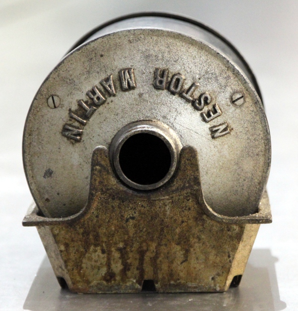 Designing a suitable
motor controller for this thing. We can either use the design done for <Fa>
(using a DCM24-40 controller) or the one for the low vibrato mechanism on the
<Tubo> robot.
Designing a suitable
motor controller for this thing. We can either use the design done for <Fa>
(using a DCM24-40 controller) or the one for the low vibrato mechanism on the
<Tubo> robot.
01.10.2020: The crank on the coffee burner connects with a 1/4" thread.
So, we made some adapter pieces to couple it to the motor. The motor, a Crouzet
24V DC motor, came in from RS Components today. It has an 8mm shaft. This is
the same type of motor as used for the low vibrato mechanism on the <Tubo>
robot.
02.10.2020: Using the 1/4" thread did not lead to acceptable results. The
lack of precision wherewith the coffee burner was made caused too much excentricity
on the axle. So we decided to drill a 6 mm hole through the burner and mounted
a dented wheel such that we can use a belt for driving the drum.
03.10.2020: First tentative mount of the chassis with the motor and first test
of the complete mechanism.
04.10.2020: Further work on the coffee burner assembly.
05.10.2020: Going on with the coffee burner... Here is a PCB for the Crouzet
motor-controller as well as a circuit drawing. This design is derived from our
previous design for the same motor type used on the low vibrato mechanism of
the <Tubo> robot.
 For the power
supply of this unit, we can use a Traco Power module TMM60124 (24V - 2.5A).
Etching, drilling and soldering of this board finished.
For the power
supply of this unit, we can use a Traco Power module TMM60124 (24V - 2.5A).
Etching, drilling and soldering of this board finished.
06-07.10.2020: Start coding firmware for the roaster. First tests... nothing
seems to work. Oscillation of the board remedied by mounting a 100uH coil instead
of the 22uH we had at first.
08.10.2020: Firmware for roaster ready. The bug we had was related to a limit
on the amount of nested if-then structures in the proton code. This code implements
ramping on speedup as well as on slowdown. PIC diary updated. A snapshot Moniek
made of me whilst working on the roaster code: 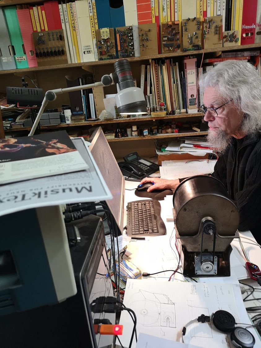 It makes an infernal noise...
09.10.2020: Industrial horn digged up: 24V - 800mA, sounding a C#, or midi 37.
Bug removed from motor firmware: motor speed is no longer oscillating around
the sollspeed value. All tests passed o.k. now.
10.10.2020: Start design of a suitable trolley. Maybe we can use nothing but
wheelchair and rollator parts...
11.10.2020: Running out of stainless steel tube 22 x 2. Could we afford to buy
new tubes or do we have to recycle? We are really running out of funds now...
13.10.2020: New stainless steel tube bought from Demar Lux...
17.10.2020: First design of the trolley.
18.10.2020: Start TIG welding works on the trolley: frontwheels mounted, the
large backwheels -from an old wheelchair- are designed such hat they can also
move sideways. Should we keep this feature? Dont know yet. 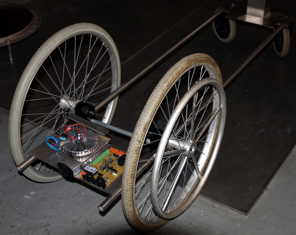
19.10.2020: Trying to connect again with the <Rumo> research started back
in 2014. We certainly need many more sound sources in this robot.
20.10.2020: digged up an old hunting horn.
21.10.2020: Preliminary calculations and measurements with the horn. It sounds
like it's a high f# tuned horn (probably an F or a G horn in some old diapason).
22.10.2020: More and more, it looks feasable, to add this horn in <Rumo>.
Maybe we can use our amplifier design around the TDA7264 chip, as used for <Chi>...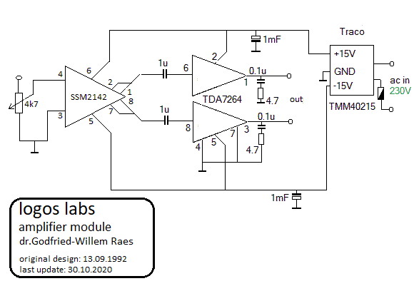
There is even a PCB designed for this circuit.
23.10.2020: Het idee om een jachthoorn toe te voegen krijgt alsmaar meer vorm.
We hebben al de hoorn, een PIC driverboard, een membaankompressor, een LM12
power-amp board en een geschikte voedingstransfo... Het LM12 board is hetzelfde
dat we ook gebruikten voor <So> in versie 3.0. Het ontwerp en het PCB
dateert van 1991. De vermogens opamp (LM12) is al lang niet meer verkrijgbaar.
24.10.2020: Voor de membraankompressor kunnen we het board gebruiken ontwikkeld
na dat voor Autosax V5.0. Dat PCB is gedateerd 03.05.2020. Als driver kunnen
we een oude Boyer (Frans) of een nieuwe Selenium driver (Brasilie) gebruiken.
Op de foto hebben we de Selenium driver gemonteerd: 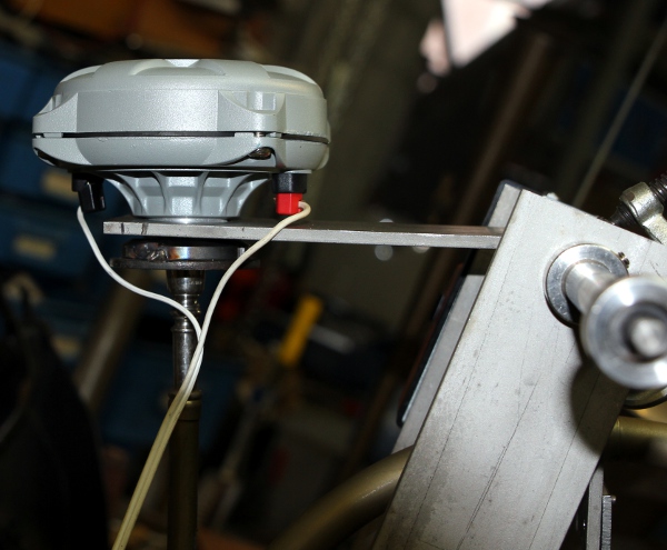
25.10.2020: Uittekenen mogelijk chassis voor de komponenten van de jachthoorn.
Een draaibare opstelling -met motor- lijkt hier aangewezen.
26.10.2020: We ontdekten nog een Belimo LM24 motor module in ons labo. Dit lijkt
wel bruikbaar voor de aandrijving van de beweging van de hoorn. Hier is het
datablad van deze Zwitserse module. Test opstelling gemaakt: het mechanisme
is marginaal sterk genoeg op de hoorn volledig op te heffen. De bewegingssnelheid
is bijzonder laag: 80 tot 120 sekonden voor het gehele trajekt van 90 graden.
Het mechanisme is wel zo goed als geruisloos. Bij een spanning van 24V DC is
het stroomverbruik slechts 40 mA.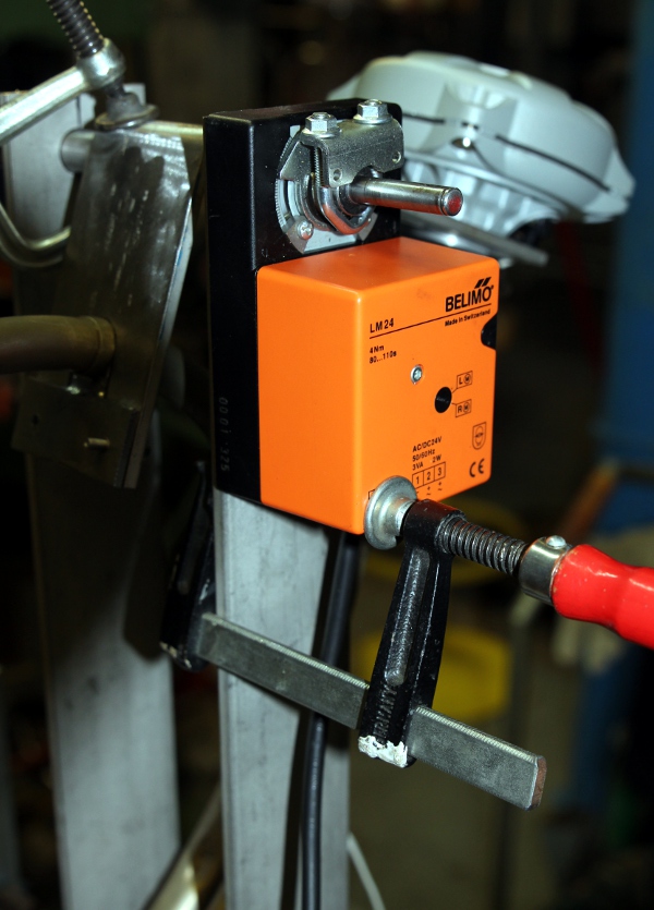 De volledige testopstelling op de lastafel ziet er nu zo uit:
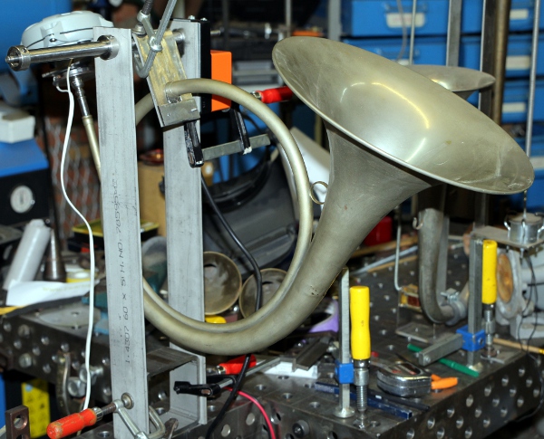
27.10.2020: Verder TIG laswerk aan de ophanging en de mechanika voor de jachthoorn.
28.10.2020: Montage van de LM12 eindversterker en de voedingstransfo op geplooide
inox plaat. Bruikbare Haller-relais opgedolven in het lab voor gebruik met de
Belimo motor:  Moeten
we ook hier weer een Penny+Giles rotation sensor toepassen, zoals we deden voor
<Ob>, <Klar> en <Fa>? Of, kunnen we met een 'eenvoudige' (maar
vandaag illegale) kwikschakelaar volstaan? Zou het mogelijk zijn de eindposities
af te leiden uit het stroomverbruik van de motor?
Moeten
we ook hier weer een Penny+Giles rotation sensor toepassen, zoals we deden voor
<Ob>, <Klar> en <Fa>? Of, kunnen we met een 'eenvoudige' (maar
vandaag illegale) kwikschakelaar volstaan? Zou het mogelijk zijn de eindposities
af te leiden uit het stroomverbruik van de motor?
29.10.2020: M4 Tap afgebroken in de montageklem voor de hoorn... Schema voor
de motorbesturingsprint uitgetekend. Dit printje is slechts 60 mm breed en past
dus eventueel op het inox opstaand profiel van de hoorndrager. Een PCB voor
deze schakeling is eveneens in voorbereiding:
30.10.2020: Verder werk aan de PCB's nodig voor de verdere afwerking/uitwerking
van de <Rumo> robot. Hopelijk vallen we niet zonder essentiele onderdelen,
want de kortzichtige en ongedifferencieerde corona maatregelen van de Belgische
regering maken bevoorrading zo goed als onmogelijk.
31.10.2020: Produktie van twee PCB's: eentje voor de Belimo motorbesturing en
eentje voor een TDA7264 mono-brugversterkertje. Beide samen passen on een eurokaart
160x100mm. De kwaliteit van de geetste printjes is ondermaats, vanwege de te
geringe zwarting van onze printer... Dit is de gebruikte film: 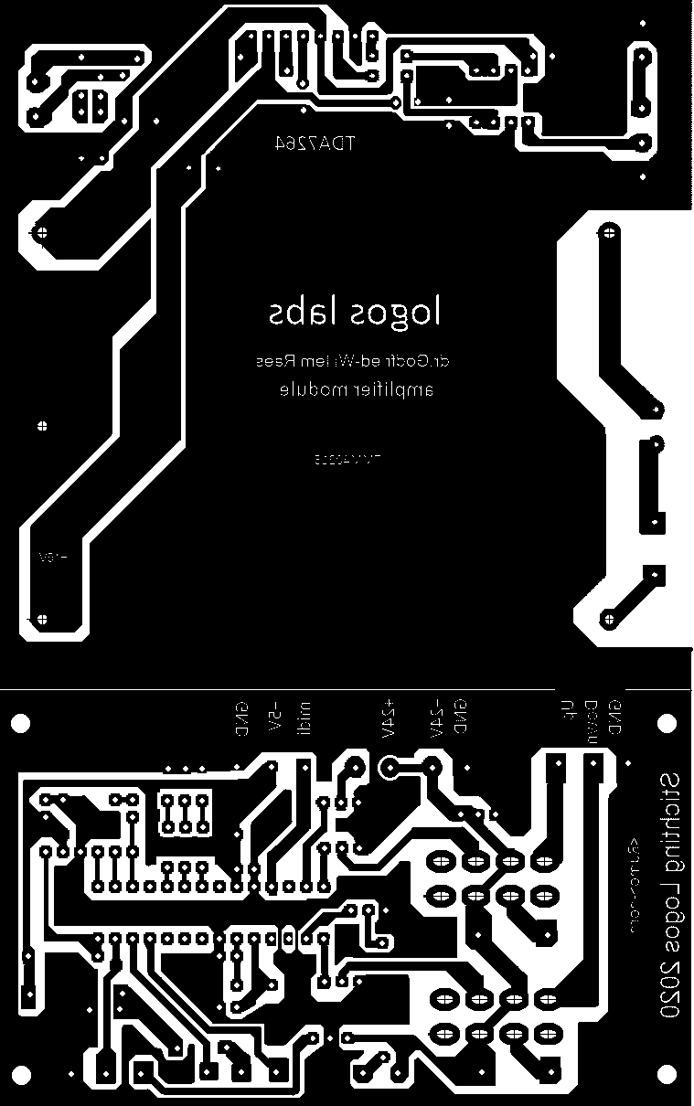
01.11.2020: Opbouw van beide printjes. Korrekties aangebracht in de PCB files.
Tests hardware. Hier is de bestukte print: 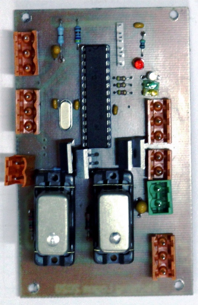
02.11.2020: Begin ontwikkeling kode van de besturing van de Belimo motor voor
de beweging van de hoorn. De kalibratie zal, gezien de traagheid van de motor,
wel behoorlijk wat tijd in beslag nemen na koude start en power-down kommando's.
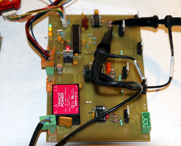
03.11.2020: Versie 1.0 van de motorbesturingsfirmware is klaar. 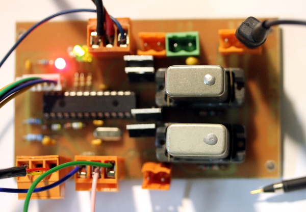 Hier ligt de print op de folterbank, gekoppeld aan de Tektronix oscilloskoop,
de PC en de Pickit3 programmer van Microchip.
Hier ligt de print op de folterbank, gekoppeld aan de Tektronix oscilloskoop,
de PC en de Pickit3 programmer van Microchip.
04.11.2020: Bestelling 24 V voedingsmodules bij Farnell: TMP60124. Bestelnummer
2280022.
05.11.2020: Werk stilgelegd omwille van het ondergaan van een PET/CT scan...
Kanker loert om het hoekje.
06.11.2020: Kwikschakelaar aangepast aan het 8 mm uitsteeksel van de 20 mm as
waarrond de hoorn kan draaien. Dit werkje volledig met de hand uitgevoerd, vanwege
het risiko op breuk van de glazen kwikschakelaar zelf.
07.11.2020: Levering van de bestelde Traco Power voeding, 24 V - 2.5 A. Konstruktie
van een chassisplaat voor de montage van deze voeding. Kablering van de motor,
kwikschakelaar en kompressiedriver.
08.11.2020: Verdere bedrading hoorn module.
09.11.2020: Ontwikkeling 18F2525 kode voor debouncing (kontaktdenderonderdrukking)
van de kwikschakelaar voor de motorbesturing van de hoorn. Eerste tests van
de motorbesturing onder spanning. De motor blijkt niet te doen wat was voorspeld...
hebben we een fout gemaakt in de bedrading van de relaisvoet? Grondig nazicht
wijst uit: inderdaad, foutief genummerd op het printontwerp. Dit moeten we dus
via een patch korrigeren. PCB ontwerp meteen ook gekorrigeerd zodat in toekomstige
versies de fout niet opnieuw zou kunnen optreden.
10.11.2020: Montage van een 24V/5W buislampje op het bewegend deel van de hoorn.
Test van de gekorrigeerde print voor de motorbesturing. Het blijkt goed te werken,
maar... een van de aansluitdraden naar de kwikschakelaar kwam al te strak onder
mechanische spanning te staan, waardoor de aansluiting naar de kwikschakelaar
afbrak. Einde van de mooie antieke kwikschakelaar. Nu zit er niks anders op
dan weer een Penny-Giles sensor (type STT280/60/P2) te gebruiken. Met de redaktie
van de firmware moeten we nu natuurlijk ook helemaal herbeginnen.
11.11.2020: TIG microwelding works: mounting plate for the sensor on the 8 mm
axle. Nieuwe versie van de firmware afgewerkt. De Penny+Giles sensor wordt nu
gevoed uit de 5V DC spanning. Een 78L12 regulator op het PCB is daarmee overbodig
geworden. Overweging om de hoorn module toch als een autonome robot verder te
bouwen. Dit is een mogelijke wielbasis voor zo'n autonome jachthoorn robot:
12.11.2020: De kogel is door de kerk: de jachthoorn gaat alleen en verlaat het
<rumo> projekt... Nu moeten we er natuurlijk een nieuwe naam voor verzinnen.
Begin konstruktie van de wielbasis... we vallen echter zonder schutgas: Argon
fles leeg. Onderkant van de basisplaat per vergissing gelast met gewone Hilco
rood elektroden in plaats van met inox elektroden...
13.11.2020: Zoektocht naar alweer een nieuwe verdeler voor Argon gas. Zou <Hunt>
een geschikte naam zijn voor deze robot?
14.11.2020: Nieuwe webpagina aangemaakt voor de nu zijn eigen gang gaande <Hunt>
robot. Hier is de link. Buisklemmen met rubberinleg
ingekocht bij Brico voor de assemblage van de diverse komponenten in Rumo.
07.12.2020: Bug gevonden en gedood in de kode voor de koffiebrander: Er zat
een fout in het uitlezen van Timer 2/3, als 32 bit timer.
15.11.2021: <Rumo> projekt opnieuw ter hand genomen, naar aanleiding van
het verkrijgen van vier Aiwa motortjes, gelabeld 24V 15U51H, verder zonder gegevens.
Ook niks te vinden op het www. De produktiedatum is 19dec80 DD-1, 05sep80 DD-1
van elke produktiedatum hebben we nu twee exemplaren. De motortjes hebben twee
in seriegeschakelde wikkelingen, elk met een DC weerstand van ca. 35 Ohm. Zijn
het AC of brushless DC motortjes?  We hebben de schakeling als AC motor getest en inderdaad, de motortjes draaien.
De kondensator mag wel niet kleiner zijn dan 20uF. Eens gestart, blijven de
motortjes draaien ook zonder de kondensator. Bij belasting vallen ze echter
uit. De induktie meting van de wikkelingen leverde volgende waarden op: rood-geel:
91 mH, blauw-geel: 84 mH, rood-blauw: 171 mH. Wanneer we het anker handmatig
doen draaien verdubbelt de induktiviteit nagenoeg. Een tentatieve berekening
van de voor AC benodigde kondensator levert dan ca. 50uF op. Een blik op de
wikkelingen wijst uit dat het om een tweepolige motor moet gaan, met twee paar
wikkelingen op de stator:
We hebben de schakeling als AC motor getest en inderdaad, de motortjes draaien.
De kondensator mag wel niet kleiner zijn dan 20uF. Eens gestart, blijven de
motortjes draaien ook zonder de kondensator. Bij belasting vallen ze echter
uit. De induktie meting van de wikkelingen leverde volgende waarden op: rood-geel:
91 mH, blauw-geel: 84 mH, rood-blauw: 171 mH. Wanneer we het anker handmatig
doen draaien verdubbelt de induktiviteit nagenoeg. Een tentatieve berekening
van de voor AC benodigde kondensator levert dan ca. 50uF op. Een blik op de
wikkelingen wijst uit dat het om een tweepolige motor moet gaan, met twee paar
wikkelingen op de stator:  Voor
gebruik als DC motor zouden we de schakeling die we in 2005 bouwden voor de
<Sire> robot kunnen gebruiken, niet met PWM echter, maar wel met vier
timers voor de vier motortjes bestuurd door een enkele PIC controller. Hier
is het schakelschema:
Voor
gebruik als DC motor zouden we de schakeling die we in 2005 bouwden voor de
<Sire> robot kunnen gebruiken, niet met PWM echter, maar wel met vier
timers voor de vier motortjes bestuurd door een enkele PIC controller. Hier
is het schakelschema:  Drie PCB's voor deze schakeling hebben we nog in voorraad. Waarvoor we deze
motorjes zouden kunnen gebruiken, valt echter nog te bezien...
Drie PCB's voor deze schakeling hebben we nog in voorraad. Waarvoor we deze
motorjes zouden kunnen gebruiken, valt echter nog te bezien...
18.11.2021: In bovenstaande aanpak is op elk ogenblik een van beide wikkelingen
bekrachtigd. Dus, de faze tussen beide is 180 graden. Een besturing met een
90 graden draaing is met dezelfde hardware ook te implementeren, maar vergt
tweemaal snellere timers:  Dat kan dus in de firmware worden opgelost.
20.11.2021: De Aiwa motortje moeten wel degelijk AC motortjes zijn. We leggen
ze -voorlopig altans- aan de kant. De firmware is getest en o.k. maar uiteindelijk
niet voor dit type motor geschikt.
14.05.2022: Bouwprojekt <Rumo> opnieuw in handen genomen... inventarisering
van de staat waarin het projekt zich nu bevindt.
26.07.2022: De nestor-martin module opnieuw aangesloten, voor mogelijk gebruik
in ons solo koncert op 18 augustus...
11.08.2022: Montage van de Nestor-Martin module op een vertikale vierkante inox
kolom (90x90), wellicht afkomstig van een Ikea lamp. Montage via twee stukken
van 270 mm 25x25x3 vierkant profiel en vier Ettinger M4 trillingsdempers.
20.08.2022: De 8-voudige wisper II module weer opgedolven en opnieuw geevalueerd
voor <Rumo>. Opnieuw gestart met de bouw van <Rumo>, al weze het
nog steeds zonder middelen...
22.08.2022: Onderstel ineen gelast, met houder voor de akoestische versterkers
voor de veren. 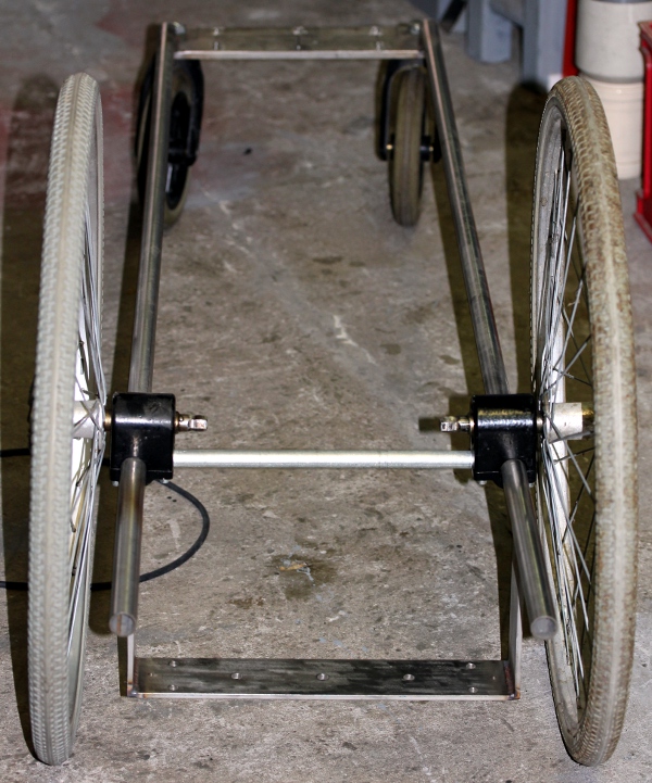
 Storing in de laspost maakt verder lassen voorlopig onmogelijk... De laspost,
een Genesis, is intussen alweer 32 jaar oud, we kochten hem voor de bouw van
de Logos tetraederzaal.
Storing in de laspost maakt verder lassen voorlopig onmogelijk... De laspost,
een Genesis, is intussen alweer 32 jaar oud, we kochten hem voor de bouw van
de Logos tetraederzaal.
23.08.2022: Ontwerp montage van de whispers en de achterzijde met netspanningsingang.
24.08.2022: TIG laswerk voor alle reeds werkende komponenten.
28.08.2022: Blijkt dat we de oorspronkelijk voor <Rumo> bedoelde midi-hub
en 12x pulse boards inmiddels voor andere robots gebruikten. We zullen dus wel
nieuwe moeten maken... Alvast nieuwe printplaat besteld bij Conrad.
31.08.2022: Overlijden Floesj...
02.09.2022: Etsen boren en bestukken nieuw midi-hub board.
05-07.09.2022: experimenten met klankproduktie spullen en motoren. Nieuwe lotto
trommel besteld.
08.09.2022: Lotto (bingo) trommel geleverd. Eerste klanktests en meting van
het nodige koppel voor de beweging ervan. Kunnen we een van onze BLDC motoren
in voorraad gebruiken?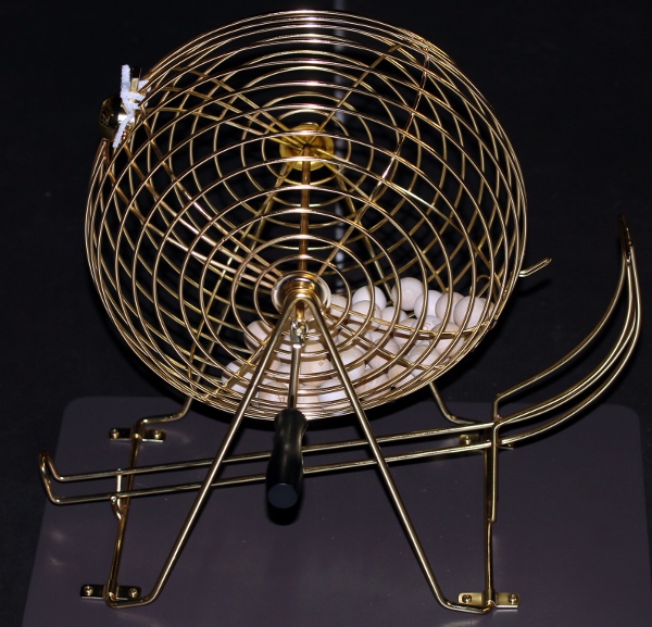
09.08.2022: Uitboren gat in messing dubbeltoeter: van 12.7 mm naar 13.7 mm voor
aanpassing op de afmetingen van een ABT-416-RC
transducer. De weerstand van dit type is 52 Ohm, de resonantiefrekwentie
2048 Hz en de stroom 40 mA. Nominale werkspanning 6 V. De resonantiefrekwentie
van de dubbeltoeter voorzien van de transducer ligt op noot 66, Fa# of 369 Hz.
10.09.2022: We hebben ook nog een toeter, afkomstig van een metalen klakson,
op voorraad; gestemd op 440 Hz. Deze kan eventueel ook met een ABT-416 transducer
worden aangestuurd.
11.09.2022: Nakijken van de potentieel bruikbare voedingen voor <Rumo>.
Kunnen we dit 12 V / 10 A exemplaar hier gebruiken? Open klem uitgangsspanning
17 V. 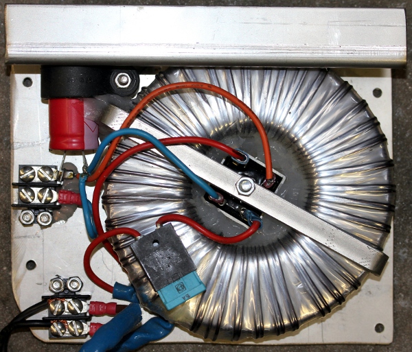 Deze voeding
is in elk geval voldoende krachtig voor de vier motor klaksons die we zouden
kunnen gebruiken. Verder stelt zich de vraag naar de zin van een dubbele toeter
aangedreven vanuit een gemeenschappelijk en symmetrisch geplaatst punt. De enige
reden voor zo'n ontwerp zou kunnen liggen in het fazegedrag voor een bewegende
waarnemer of bij gebruik op een bewegend voertuig.
Deze voeding
is in elk geval voldoende krachtig voor de vier motor klaksons die we zouden
kunnen gebruiken. Verder stelt zich de vraag naar de zin van een dubbele toeter
aangedreven vanuit een gemeenschappelijk en symmetrisch geplaatst punt. De enige
reden voor zo'n ontwerp zou kunnen liggen in het fazegedrag voor een bewegende
waarnemer of bij gebruik op een bewegend voertuig. Immers voor een zijwaartse waarnemer, kunnen er amplitudeschommelingen waarneembaar
zijn wanneer de geluidsbron in beweging is omdat er een fazeverschil kan bestaan
tussen het geluid vertrekkend vanuit de twee geluidsbronnen.
Immers voor een zijwaartse waarnemer, kunnen er amplitudeschommelingen waarneembaar
zijn wanneer de geluidsbron in beweging is omdat er een fazeverschil kan bestaan
tussen het geluid vertrekkend vanuit de twee geluidsbronnen.
01.10.2022: Experimenten met de nieuwe lotto-trommel: de zware klep voor de
selektie van het uitvallende/winnende bolletje hebben we verwijderd en vervangen
door een messing buisje zodat de bolletje er niet uitvallen. Test gedaan met
diverse motoren: de BLDC motor heeft een te gering koppel om de trommel te doen
starten. Een AC motor (Crouzet) met 1:625 vertragingskast zou kunnen werken,
maar zelfs die is maar marginaal voldoende sterk. Een riemaandrijving dient
zich hier aan.
04.10.2022: Laswerk: montageplaat voor het midi hub board op het achterdeel
van het chassis gelast.
11.10.2022: Bezoek Jan Jambon aan het robotorkest: demo gegeven en problemen
besproken.
13.10.2022: Verdere experimenten met klankgeneratoren voor Rumo.
17.10.2022: Levering van RS-components: geared DC motor, 40 rpm, 24 V, 20 W.
RS artikel nr. 3808649. Tests met kettingoverbrenging, schetsen mogelijke montagewijzen.
De kettingoverbrenging blijkt nodeloos gekompliceerd en een rechtstreekse aandrijving
op de as doorheen de kooi ligt voor de hand.
22.10.2022: Uitsnijden RVS voor montage motor. Konstruktie van een askoppeling.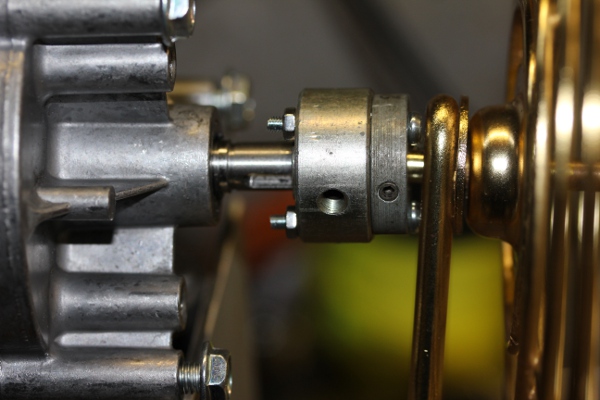 De motoras heeft een diameter van 9 mm terwijl de as doorheen de kooi slechts
6 mm meet.
De motoras heeft een diameter van 9 mm terwijl de as doorheen de kooi slechts
6 mm meet.
23.10.2022: Boormal overgebracht op RVS stukken. Montage motor met 6 mm kogellager
op het vrije uiteinde.De gehele oorspronkelijke draagstruktuur kunnen we nu
gewoon aan de afvalhoop toevertrouwen.
24.10.2022: Laswerk aan de kooimodule. Mechanische tests. De 4 membraanklaksons
werkend op 12 V DC kunnen op deze module een geschikte plaats vinden. Montage
met M6 boutjes. Ook voor twee rode LED-strips kunnen we wat plaats voorzien.
25.10.2022: Overzicht voor de <Rumo> robot opnieuw uitgetekend. Door de
vele wijzigingen onderweg, was aan het bestaande en oorspronkelijke plan nauwelijks
nog uit te geraken. Het besturingsboard ontworpen en gebouwd voor de <Balsi>
robot in september 2017 en oorspronkelijk bedoeld voor de besturing van een
3-fazen 230V/50Hz induktiemotor, blijkt nu bruikbaar te zijn als klankgenerator
voor de besturing van drie konische toeters. Een TMPM Traco voedingsmodule (12V,
300mA), die we nog niet op de print hadden gesoldeerd, hebben we zelfs nog in
de labo voorraad gevonden. Hier is het schema:  Door een van de pwm uitgangen van elk van de drie onafhankelijk bestuurbare
uitgangen in fase te moduleren, kunnen we een ADSR en/of volume kontrole implementeren
in de firmware. De 1 uF kondensatoren op de uitgangen moeten wellicht door draadbruggen
vervangen worden. De ICL7667 drivers moeten voldoende krachtig zijn om ABT416-RC
buzzers aan te sturen.
Door een van de pwm uitgangen van elk van de drie onafhankelijk bestuurbare
uitgangen in fase te moduleren, kunnen we een ADSR en/of volume kontrole implementeren
in de firmware. De 1 uF kondensatoren op de uitgangen moeten wellicht door draadbruggen
vervangen worden. De ICL7667 drivers moeten voldoende krachtig zijn om ABT416-RC
buzzers aan te sturen.
27.10.2022: Door de inverters op de uitgangen (ICL7667 drivers) kunnen we een
simpele NAND opbouwen met twee Shottky diodes aan de uitgangen. Voor de Pi-reeks
hadden we AND poorten op de uitgangen van de PIC met positieve logika. De inverters
maken het nu mogelijk om met ongewijzigde logika en kode, NAND's toe te passen
op de uitgangen. Eerste aanpassing van de kode uitgaande van de firmware voor
de <4Pi> robot. De 1 uF kondensatoren op het PCB kunnen we lossolderen
en vervangen door Shottky diodes.
28.10.2022: Deze aanpak blijkt niet te werken. Dan maar de AND-poort gerealiseerd
met zes SMD Shottky diodes gesoldeerd tussen de uitgangen van de PIC en de ICL7667
drivers. Dit blijkt te werken!
29.10.2022: Tests met de twee lange messing toeters. Afdraaien aangepast mondstuk
voor een eerste toeter, uitgaand van een oud russisch trompetmondstuk. Dit kan
worden aangestuurd met een ABT416RC buzzer, ook al is de haalbare geluidsterkte
nogal aan de lage kant.  Beide
toeters zijn even lang, maar een ervan gaan we inkorten zodat hij een halve
toon hoger klinkt.
Beide
toeters zijn even lang, maar een ervan gaan we inkorten zodat hij een halve
toon hoger klinkt.
30.10.2022: Boventoonreeksen geprogrammeerd in de firmware voor de hooters.,
Hiermee wordt een zekere mate van polyfonie toch mogelijk.
31.10.2022: Testkode geschreven en toegevoegd in GMT. Impedantie van de ABT416RC
buzzers nagemeten: de induktie is 7.5mH bij 100 Hz, 7.6mH bij 120 Hz, 7 mH bij
1kHz en 4.47 mH bij 10kHz.
01.10.2022: Meerdere mondstukken voor de grote hooters afgedraaid op de draaibank:
met kapilair en laval-tuit. De geluidsterkte wordt niet substantieel groter
met deze alternatieven.
02.11.2022: Firmware voor de hooters verder ontwikkeld: de ruiskomponent in
de klank van de hooters sterk verbeterd. De besturing blijft via controller
#1.
05.11.2022: TIG laswerk: montage van de whisper komponent op het chassis.
06.11.2022: Bestudering van de mogelijkheden om ook een bel-rammelaar uit keramiek
op de nemen in het bouwprojekt: Een
motortje met vertragingskast hebben we nog, een askoppeling en een gelagerde
drager moeten we nog mogen. De vastklemming met twee M8 trillingsdempers is
een goed idee.
07.11.2022: Inox plaat uitgesneden en geplooid voor montage op de achterzijde.
08.11.2022: Lassen plaat achterzijde. Ontwerp van een stuurstang, vast te lassen
op de achterzijde.
09.11.2022: Experimenten rond de bouw van een 8-voudige shakermodule waarbij
we gebruik kunnen maken van de Siemens elektromagneten unit die we oorspronkelijk
bouwden voor de castagnetten in de eerste versie van onze <Vox Humanola>
robot. Deze magneten, ingegoten in blauwe kunsttof dragen 1985 als produktiedatum
maar zijn zo goed als nieuw.. De evaluatie van deze experimenten vertrouwenden
we toe aan Mattias Parent.
10.11.2022: Atelier bezoek van Jocelyn Robert uit Quebec. Demo robotorkest.
11.11.2022: Sluitstukken gemaakt voor de vaste montage van de wielen en de remmen.
Voor deze onderdelen gebruikten we messing.
12.11.2022: Oude PCB's opgedolven oorspronkelijk gemaakt voor <Balsi>
om te werken als 3-faze motorcontrollers voor 230V inductiemotoren. Dit ontwerp
bleek echter niet goed te werken... de boards en de code zijn in orde en dus
kunnen deze ontwerpen bruikbaar zijn in een funktie als 3-kanaals PWM besturing
of toongenerator. Hier is het oorspronkelijke schakelschema:  De
kode werd uitvoerig getest op de funktionele print zonder gemonteerde vermogensmosfets:
De
kode werd uitvoerig getest op de funktionele print zonder gemonteerde vermogensmosfets:
 De opgebouwde PCB
met de vermogensmosfets bedoeld voor <Balsi>, maar dus gesneuveld tijdens
de proeven met aangesloten motor:
De opgebouwde PCB
met de vermogensmosfets bedoeld voor <Balsi>, maar dus gesneuveld tijdens
de proeven met aangesloten motor: 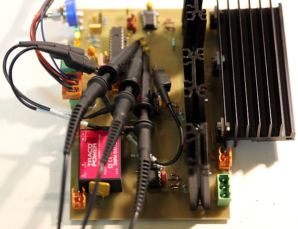
13.11.2022: Verder uitwerken van de bouwplannen.
28.11.2022: Firmware voor de whisper-2 komponent helemaal herschreven. Nu gebruik
makend van 10-bit PWM voor de ventilatorbesturing. De PWM frekwentie komt nu
op 25 kHz te liggen, overeenkomstig de application note voor de gebruikte ventilatortjes
van Sanyo.
01.01.2023: Iedereen is nu ontslagen bij Stichting Logos. We staan er weer helemaal
alleen voor. Hoe we de verwarming nog moeten betalen is een raadsel... Anders
dan kapitaalkrachtige operabedrijven zoals de Muntschouwburg, hebben wij niet
de middelen om muzikologen -of wat sinds Taruskin daarvoor nog moet doorgaan-
in te schakelen om onze produktie tot wetenschappellijke waarheid te doen konsakreren...
Bij socialisten is korruptie duidelijk nooit ver weg.
19.01.2023: Werkzaamheden aan <Rumo> opnieuw opgenomen. De afwerking kan
problematisch worden, nu ook Stad Gent -op instigatie van Vooruit- onze vaste
werkingstoelage helemaal schrapte...
18.02.2023: Module met de draaiende keramiek-bellen afgewerkt en elastisch gemonteerd
op het chassis. Metingen aan het geheel met motor en belasting:
| Spanning | Stroom | notas |
| 1.8V | 100 mA | minimale draaispanning |
| 2.5V | 110mA | |
| 5V | 125 mA | |
| 7 V | 135 mA | |
| 9 V | 150 mA | |
| 12 V | 160 mA | |
| 14 V | 165 mA | |
| 15 V | 170 mA | maximale werkspanning nominaal |
| 20 V | 200 mA | |
| 24 V | 205 mA | |
| 30 V | 240 mA |
Het nominaal spanningsbereik opgegeven door de fabrikant is 4.5 V tot 15 V.
Voor de besturing zouden we een reserve board gemaakt voor de besturing van
de Belimo motor in Hunt kunnen gebruiken. Geen van de overige reeds voorziene
boards heeft immers nog een vrij PWM kanaal beschikbaar. Hier is het schema:
 De uitgang
voor de bidirectionele solenoide zouden we kunnen gebruiker voor een shaker
mechanisme op 24V, zoiets zoals gebruikt voor <Tinti> bvb.
De uitgang
voor de bidirectionele solenoide zouden we kunnen gebruiker voor een shaker
mechanisme op 24V, zoiets zoals gebruikt voor <Tinti> bvb.
19.02.2023: PCB voor de besturing -oorspronkelijk ontworpen voor <Hunt>,
Belimo motor, aangepast aan de nieuwe funktie. Het heeft immers geen zin het
nog als spare-board opzij te houden omdat er niemand meer is om er in de toekomst
nog voor te zorgen... Begin redaktie van de firmware voor dit board.
20.02.2023: Firmware voor de besturing van de keramiek bellen afgewerkt in de
Positron compiler. Nog een volle lengte groene LED strip opgedolven, werkend
op 24V en dus ideaal geschikt voor besturing door dit board...
21.02.2023: Hoge koorts en keelpijn, maar traag gaan we toch door...
23.02.2023: Clay-bell module helemaal afgewerkt: voorzien van drie onafhankelijke
groene LED strips en alle bijhorende firmware. De module wordt met twee beugels
en twee M10 bouten op het <Rumo> chassis bevestigd. 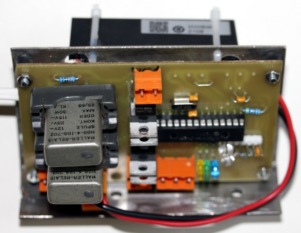
24.02.2023: Precision drilling of mounting holes, M10 and M12. Begin ontwikkeling
kode voor het hub-board. Dit board moet de lange veren aansturen evenals de
Bingo trommel. Overview opnieuw uitgetekend in funktie van de nieuwste wijzigingen.
De voeding voor de komponenten aangestuurd door het hub-board moet een 24V exemplaar
zijn. We hebben nog een XP power 6.5A module op voorraad. Voor de aansturing
van het rode zwaailicht kunnen we een optisch relais gebruiken. Opto22, model
MP240D4 hebben we ook nog op voorraad.
26.02.2023: Optorelais gemonteerd op het hub board en aangesloten op poort PA.1
. Tests o.k. Firmware aangepast.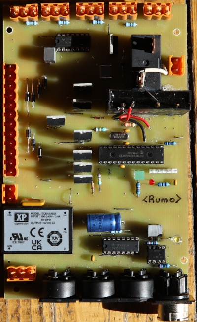
01.03.2023: Verder werk aan het chassis en de konstruktie van een stuur/handvat.
03.03.2023: Chinese oranje zwaailichten geleverd. Ze blijken echter behept met
allerlei ingebouwde lichtshow programma's waarvan we nu nog moeten uitvissen
hoe we die kunnen kwijtgeraken...
18.04.2023: Nu <Kazumi> is afgewerkt, weer de draad opgenomen voor <Rumo>...
19.04.2023: Stuurhandvat gelast in 25 mm inox buis met twee voorgevormde lasbochten.
Het ware goed twee radar sensoren te voorzien op de voorkant zodat deze robot
volledig stand-alone zou kunnen funktioneren.
30.04.2023: Tests en experimenten uitgevoerd met oude vibrators: 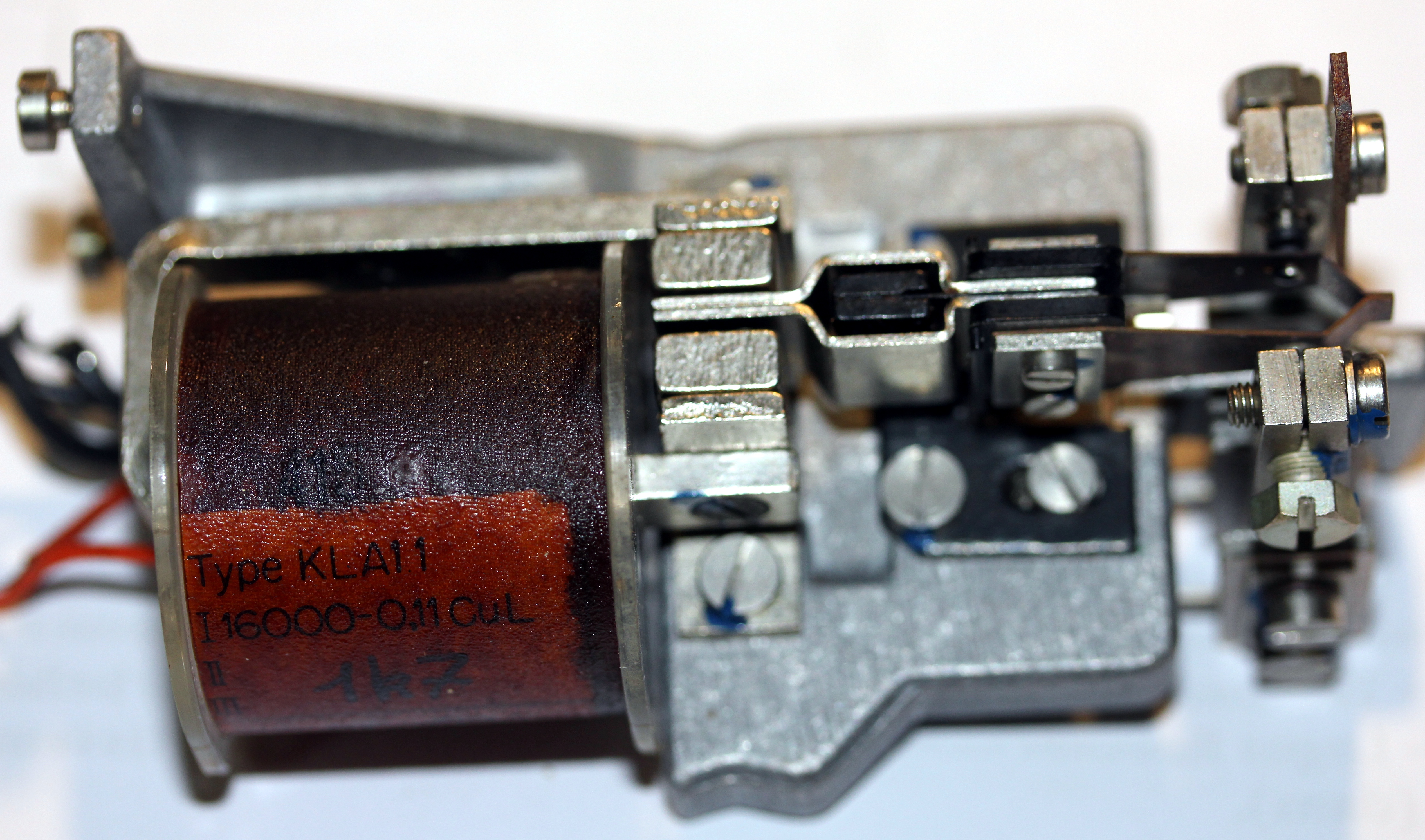 Wanneer
we de spoel aansturen met een audio amp, opgebouwd alsvolgt:
Wanneer
we de spoel aansturen met een audio amp, opgebouwd alsvolgt: 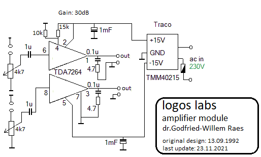 blijkt
de triller toch niet te doen wat we ervan hadden verwacht. Moet de aansturing
met (gepulste) DC gebeuren? De spoelweerstand van 1700 Ohm suggereert een hogere
werkspanning dan de 20Vpp die onze versterker levert. Maar ook met een kleine
transfo waarmee we de spanning verdrievoudigden, bleek het niet goed te werken.
Hoewel de zaak erg heet loopt, kunnen we met de versterker en een chinees hoogspanningsspoeltje,
toch een gemoduleerd plasma trekken tussen de polen van de autobougie. De geluidsterkte
is evenwel vrij gering...
blijkt
de triller toch niet te doen wat we ervan hadden verwacht. Moet de aansturing
met (gepulste) DC gebeuren? De spoelweerstand van 1700 Ohm suggereert een hogere
werkspanning dan de 20Vpp die onze versterker levert. Maar ook met een kleine
transfo waarmee we de spanning verdrievoudigden, bleek het niet goed te werken.
Hoewel de zaak erg heet loopt, kunnen we met de versterker en een chinees hoogspanningsspoeltje,
toch een gemoduleerd plasma trekken tussen de polen van de autobougie. De geluidsterkte
is evenwel vrij gering...
01.05.2023: De triller werkt alleen goed met gepolariseerde DC pulsen. Om enige
mechanische kracht te verkrijgen moeten we toch wel een spanning toevoeren in
de grootteorde van 100V. Uitzoeken van ombouw van een antieke membraankompressor
zodat we hem voor een toeter in <Rumo> zouden kunnen gebruiken.
01-02.05.2023: Aida trompet -eigenlijk een klaroen- voorzien van een historische
membraankompressor. De grondtoon van deze toeter is SiB (Bes), midi noot 46.
Moeten we deze klaroen inzetten in plaats van een der hooters? Of, kunnen we
een extra PCB gebruiken en dan zelfs nog twee toeters toevoegen?
03.05.2023: Verder testen en meten met de Aida trompet. De membraankompressor
heeft een DC weerstand van 152 Ohm. Uitsturing met 10V rms levert een behoorlijk
luid signaal op. Een trompetachtig geluid wordt verkregen bij uitsturing met
een rechthoeksgolf. 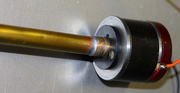
04.05.2023: Verder werk aan de ombouw van het gerecycleerde balsi board. Wanneer
we daarmee ook ABT416 buzzers aansturen, lopen die wel erg heet... Een probleem
is wel, dat de uitgangen van dit board in rust aan de negatieve voeding liggen.
Voor bipolaire uitsturing moeten we dan een kondensator tussenschakelen. We
kunnen ook in de manual van de PIC duiken om uit te zoeken hoe we de rusttoestand
van de pinnen kunnen programmeren...
05.05.2023: De voeding voor de drivers moet een symmetrische voeding zijn bvb.
-15V - 0V - +15V. Wanneer we een 2x100V voeding toepassen, moet het rechtstreeks
aansturen van megafoonspeakers mogelijk zijn. In rust , met de enable ingangen
van de MOSFET drivers op nul, is de uitgang van de driver Hi-Z en vloeit er
dus geen stroom door de belasting. Verder werk aan de firmware. Dit loopt nu
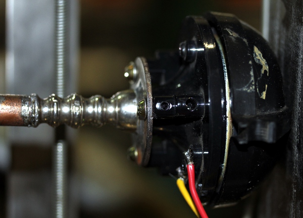
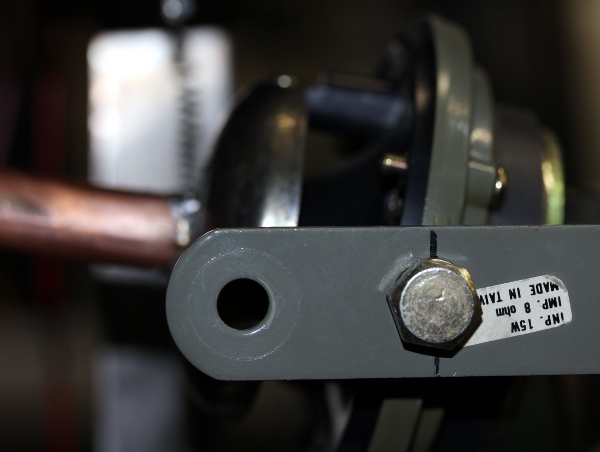
goed. Motor kompressor driver gedemonteerd uit het oude 'Klankspoor' projekt.
Dit is een 8 Ohm driver met een vermogen van 15 Watt, made in Taiwan. Het schema
van de schakeling na de uitgevoerde wijzigingen komt er nu zo uit te zien: 
06.05.2023: De 8 Ohm driver middels een speciaal ineengesoldeerd aanpasstuk
op een messing toeter aangepast. Opmeting resonantiefrekwenties met sinusoidale
uitsturing: 178Hz, 337Hz.497Hz, 677Hz, 834Hz, 1201Hz. Meer meetresultaten zijn
weer te vinden in de bouwnotas voor <Rumo>.
07.05.2023: De midi mapping voor <rumo> ziet er nu -voorlopig- zo uit:
 Op het synth2
board -het bordje dat we uit het Balsi projekt recycleerden- hebben we nu per
bazuin telkens zes verschillende toonhoogtes geimplementeerd. Gaten in de tessituur
zijn er nog steeds, van hoog naar laag: 92, 91, 75, 72, 68, 67, 63, 61, 60,
59. Bij de experimenten met het synth2 board is helaas de bijna honderd jaar
oude membraankompressor gesneuveld... We hadden het vermogen duidelijk te hoog
ingeschat. Voor de thebaanse trompet moeten we nu wel een Boyer kompressor gebruiken
en een heel nieuw koppelstuk maken. Laswerk opnieuw aangevat: achterstuk met
stuurhandvat op het chassis vastgelast. Drager voor de drie grote toeters ontworpen
en van de nodige montagegaten voorzien. Hooter 2 kan met de oorspronkelijke
beugel en twee M8 bouten orienteerbaar vastgezet worden. Hooter 1 heeft alleen
een centrale M6 bout nodig, terwijl voor de Boyer kompressor een gat van 35
mm nodig is.
Op het synth2
board -het bordje dat we uit het Balsi projekt recycleerden- hebben we nu per
bazuin telkens zes verschillende toonhoogtes geimplementeerd. Gaten in de tessituur
zijn er nog steeds, van hoog naar laag: 92, 91, 75, 72, 68, 67, 63, 61, 60,
59. Bij de experimenten met het synth2 board is helaas de bijna honderd jaar
oude membraankompressor gesneuveld... We hadden het vermogen duidelijk te hoog
ingeschat. Voor de thebaanse trompet moeten we nu wel een Boyer kompressor gebruiken
en een heel nieuw koppelstuk maken. Laswerk opnieuw aangevat: achterstuk met
stuurhandvat op het chassis vastgelast. Drager voor de drie grote toeters ontworpen
en van de nodige montagegaten voorzien. Hooter 2 kan met de oorspronkelijke
beugel en twee M8 bouten orienteerbaar vastgezet worden. Hooter 1 heeft alleen
een centrale M6 bout nodig, terwijl voor de Boyer kompressor een gat van 35
mm nodig is.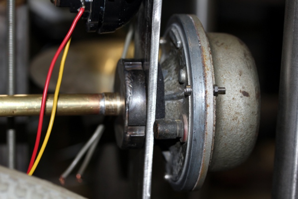
08.05.2023: Laswerk: bevestigingen voor de toeters op de vertikale vierkante
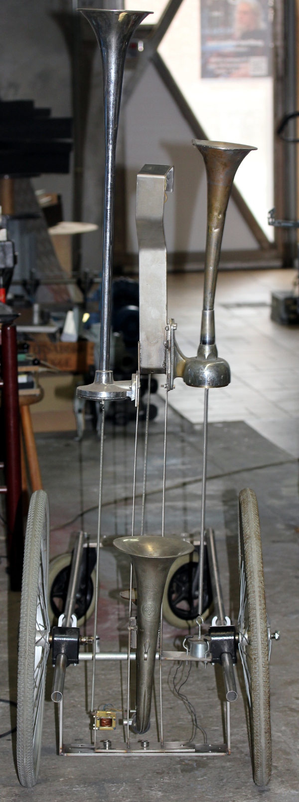
kolom gemonteerd. Zes toeters hebben al een vaste stek gevonden. Voor de 'posthoorn'
toeter moeten we nog een oplossing verzinnen.
Op de foto, <Rumo> in opbouw in ons atelier. Nog veel werk aan de winkel...
09.05.2023: La-toeter van zwarte verf ontdaan: nu weer messingkleur. De rode
kleur aan de binnenkant kunnen we wel laten. Thebaanse trompet wat opgeblonken.
Koelvinnen op het omgebouwde balsi-motor board verwijderd. De MOSFETS vertonen
zelfs geen spoor van opwarming bij de grootst denkbare belasting hier. Montage
van de DDR toeter en van de kleine 'posthoorn'. Die DDR toeter kunnen we wellicht
toch beter rood spuiten. Startproblemen van onze Genesis laspost spelen ons
weer parten..
10.05.2023: Vaste plek voor de DDR toeter uitgezocht en definitief gemonteerd.
Plaatsing IEC net-ingang en start van bedrading. Hub board vastgezet op het
chassis. SMPS voeding 24V / 6.5A gemonteerd en aangesloten.
11.05.2023: Kleine megafoonspeakers besteld in China geleverd. Heel bruikbaar
als drivers voor onze hooters. Experimenten met de driver voor noot 27. De vibrator
driver moet met een wisselende polariteit aangestuurd worden, wat niet kan met
het hub board. Een motortje met een tandwiel is ook een mogelijkheid, maar daarvoor
zou PWM dan weer aangewezen zijn... Misschien moeten we hiervoor toch een sire-board
inzetten.
12.05.2023: Verdere bedrading van het midi-hub board.
13.05.2023: Opbouw en afwerking van de rasptoeter. Hiervoor gebruiken we een
lengte stalen gordijnveer, een motortje met planetaire vertragingskast van Philips
(24V) en een meccano-wieltje voor snaaraandrijving.
14.05.2023: Montage van het tweede synth board op de vierkante vertikale kolom.
Alvast wat meer bedrading uitgevoerd.
15.05.2023: Zoektocht naar een geschikte voeding voor het tweede synth board.
Maximaal 2x15V / 3A, minimaal 2x9V / 3A. Twee goedkope 12 V -2 A XP-Power modules
kan natuurlijk ook... Laswerk en konstruktie van het onderchassis als draagstruktuur
voor de diverse voedingskomponenten. Hiervoor gebruiken we twee lengtes van
1 meter inox vierkante buis 25 x 25 mm.
16.05.2023: Verder werk aan het onderchassis: plaatsbepaling boorgaten en aanmaak
draagplaten in polykarbonaat.
17.05.2023: Bedrading verder uitgewerkt. Eerste elektrische tests: many bugs...:
whisper deed niks -de firmware stond nog op kanaal 11 ingesteld en ook de mapping
was helemaal fout. De koffiebrander stond ook op een foutief kanaal. Het hub-board
deed niks: hier bleken we alle mosfet's foutief ingesoldeerd te hebben... Na
remediering van alle ontdekte bugs blijft nu juist nog de DDR-toeter doof.
18.05.2023: Wiring bug in the largest hooter module solved. Notes 50 and 52
swapped. Watch out: the -12V is at ground and the center 0V should not be grounded.
This was a serious bug leading to a short on the -12V supply module...
19.05.2023: Na de eerste publieke demonstratie met mijn 'Voorlopig rumoer voor
Rumo' stukje, bleken er toch nog wat ernstige bugs in de hardware of de firmware
van de besturing voor de lage hooters te huizen. De amplitude-gerelateerde parameters
werken niet zoals het hoort.
20.05.2023: De problemen met de IR2104 chips, waarmee we ook al te maken kregen
bij de bouw van <Synchrochord> en <Balsi>, duiken opnieuw op. De
ellendig slechte dokumentatie van deze chips en het totaal gebrek aan deugdelijke
application notes spelen ons opnieuw parten. Na vele uren zoekwerk en heel wat
doorgebrande MOSFET's en elko's de zaak toch redelijk aan de praat gekregen.
Om de zaak koel te houden, kunnen we best 20 Ohm weerstanden in serie plaatsen
met de 16 Ohm drivers en 27 Ohm voor de 8 Ohm driver. Onze toepassing verschilt
nochtans in weinig opzichten van die gepubliceerd in een application note van
de fabrikant: 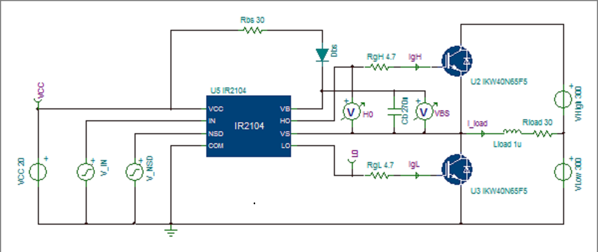 De DDR
hoorn die niet werkt is gelegen aan een niet goed gesoldeerde pin van de mosfet
waarmee hij wordt aangestuurd.
De DDR
hoorn die niet werkt is gelegen aan een niet goed gesoldeerde pin van de mosfet
waarmee hij wordt aangestuurd.
21.05.2023: Afzonderlijke controllers geimplementeerd voor de volumes van de
lage hooters. Monitoring LED's (blauw, oranje, geel) geimplementeerd. De 470
kOhm ontlaadweerstandjes aan de gates van de mosfet's vormen met de kapaciteit
van de gates (geschat op 1 nF) een low-pass met een tijdkonstante van ongeveer
470 us. Zo kunnen we 'cross-conduction' vermijden bij het Hi-Z maken van de
IR2104 uitgangen. Brandalarm bel gemonteerd en gemapt op noot 40, hoewel ze
eigenlijk als noot 76 klinkt. Deze mapping werd bepaald omdat we anders in konflikt
komen met de hooters. Firmware
voor de hub aangepast. Er blijkt toch nog een crash konditie te zijn voor de
noot 52 hooter op het synth2 board. Shaky IR2104 chip?
22.05.2023: We blijken heus niet de enige te zijn met grote problemen bij de
toepassing van de IR2104 chips: het bootstrap-principe kan alleen goed werken
wanneer pin 2 doorlopend geschakeld wordt aan een frekwentie van minstens zo'n
10kHz... De pwm voor de amplitudes nooit 100% laten zijn zou kunnen een deel
van een mogelijke remedie zijn. We implmenteerden dit in de firmware door de
Volfaktorx variabelen nooit groter te laten zijn dan 0.95. Falende mosfet op
het hub board hersteld: die bleek niet ingesoldeerd te zijn.. Zoektocht naar
extra geluidjes: schudblikjes, Afrikaanse klappers...
23.05.2023: Twee schudblikjes gebouwd en gemonteerd op de houten drager van
de whisper-module. We moeten wel een beter granulaat zien te vinden voor de
vulling van deze blikjes. Hagel? Een reserve-exemplaar van het board gebouwd
voor de <Sire> robot opnieuw geprogrameerd voor gebruik als 10 kanaals
PWM controller: hierbij gebruiken we timer 3 als pwm frekwentiegenerator en
de acht uitgangen van het board als individueel stuurbare PWM kanalen. Vier
van de uitgangen kunnen we gebruiken voor de besturing van de klaksons. De
firmware is gedokumenteerd in de bronkode voor deze microcontroller. We gingen
uit van de kode voor eenzelfde board gebruikt voor <Steely>.
24.05.2023: Verder werk aan de firmware voor het gewijzigde sire board. Kleine
buzzer omgebouwd, deze kan ook met pwm aangestuurd worden. Originele
Gnawa klappers opgedolven en ontwerp voor automatisering ervan uitgetekend.
25.05.2023: Bouw van de Gnawa klapper eenheid. Op dat de klappers goed zouden
kunnen glijden, vervaardigden we alle onderdelen in kontakt met de klappers
uit massief PTFE (Teflon). Voor de bekrachtiging gebruiken we twee Emessem trekmagneten.
Die werken echter best met heel wat hogere spanningen dan de hier beschikbare
12V/17V....
26.05.2023: Afwerking van de Gnawa klapper-eenheid. Afwerking en montage van
de Teflon blokken.
27.05.2023: Verdere montage van de <Rumo> robot. Konstruktie van een montagebeugel
voor de klapper-eenheid, zodat deze eenvoudig te verwijderen is uit de gehele
konstruktie. De beugel houdt de eenheid vast met een drietal M6 boutjes.
28.05.2023: Vastzetten van de Bingo trommel. Verder uitwerken van de test en
evaluatiekode in GMT. Konstruktie en montage van de derde shaker, waarvoor we
gebruiken maken van een kleine gemodificeerde traktuurmagneet van August Laukhuff.
Eigenlijk is dit de grootste
van de drie shakers of rammelaars die deel uitmaken van <Rumo>. Als schudmateriaal
gebruikten we hier kogels uit oude kogellagers. De rammelaar zelf is een oud
zoutvatje.
29.05.2023: Afwerking van het gemodificeerde sire PCB. Hier is het nieuwe schema:
 Bedrading van bijna
alle door dit board bestuurde komponenten. Eerste tests...: niks blijkt te werken.
Bedrading van bijna
alle door dit board bestuurde komponenten. Eerste tests...: niks blijkt te werken.
30.05.2023: debug sessie, nameten bedrading en voedingsspanningen. Zijn we wel
zeker dat de L298N chips nog in goede staat verkeren? Er bleken nog wat bugs
in de firmware te steken. Rode LED strips rechts ( 2x 12V in serie geschakeld
om te werken op 24V) bedraad en getest. Orange zwaailicht bedraad, maar dit
blijkt het om een of andere reden niet te doen. De shaker werkt goed evenals
de klaksons, al zijn die laatste veel te luid... De gnawa klappers doen het
(nog) niet, maar dat is wellicht te wijten aan te korte pulsen in de firmware.
31.05.2023: Verder werk aan de bedrading en de firmware. De
lichten blijken nu te werken evenals de klappers en de shaker, maar de buzzer
blijft alsnog pieredood. Na wat zoeken bleek dat de 1-transistorschakeling in
de buzzer niet werkt met PWM. Na plaatsing van een 330nF kondensator parallel
over de aansluitingen, blijkt alles weer prima te werken. Dat het PCB -uit 2005-
geen ICD programmeer konnektor heeft, speelt ons nu parten, vooral vanwege de
wat moeilijke bereikbaarheid van het board in de robot. Daarom maakten we een
programmeerkonnektor, uitgaand van een IC-knijper.
De
lichten blijken nu te werken evenals de klappers en de shaker, maar de buzzer
blijft alsnog pieredood. Na wat zoeken bleek dat de 1-transistorschakeling in
de buzzer niet werkt met PWM. Na plaatsing van een 330nF kondensator parallel
over de aansluitingen, blijkt alles weer prima te werken. Dat het PCB -uit 2005-
geen ICD programmeer konnektor heeft, speelt ons nu parten, vooral vanwege de
wat moeilijke bereikbaarheid van het board in de robot. Daarom maakten we een
programmeerkonnektor, uitgaand van een IC-knijper.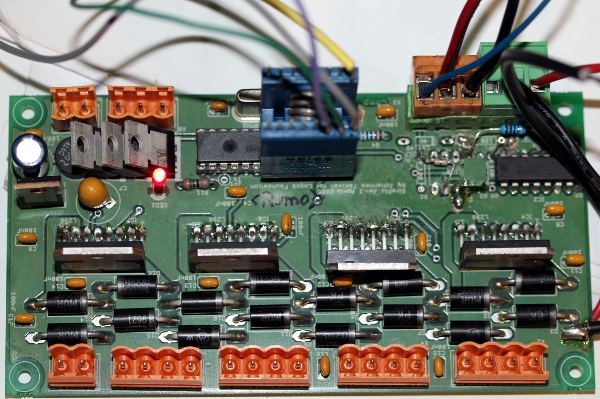 Voor het vastzetten van de bingo-trommel lasten we nu ook hier een beugel. De
trommel is nu met twee M6x25 bouten op het chassis vastgemaakt en kan makkelijk
worden losgenomen.
Voor het vastzetten van de bingo-trommel lasten we nu ook hier een beugel. De
trommel is nu met twee M6x25 bouten op het chassis vastgemaakt en kan makkelijk
worden losgenomen.
01.06.2023: De gnawa klappers werken nu goed met wat langere pulsen in de firmware.
Toch overwegen we om op 48V te laten werken om een betere dynamiek te verkrijgen.
Om een of andere reden, werkt de buzzer plots weer niet meer, ondanks de 330nF
kondensator...
02.06.2023: Firmware voor het ex-sire board geoptimaliseerd. Nu met volledige
implementatie van noot-herhalingen. Testkode in GMT aangepast.
03.06.2023: De Moflash buzzer had klaarblijkelijk een intern wakkel kontakt.
De parallel kondensator moet 220nF zijn, blijkens experimenten met de kondersatorbank.
Een klein RC-filtertje ware wellicht nog beter. Montage van het rode zwaailicht
op de voorkant van de robot. Daar moeten ook de radars een plaatsje krijgen.
04.06.2023: Stemmen van de klaksons... met oorbescherming. Probleem is dat die
stemming niet stabiel blijkt te zijn... Het rode zwaailicht werkt nu, maar er
zat een bug in het hub board, waardoor bij het aanzetten van de robot, het rode
zwaailicht in werking trad. De lamp - met ba15d fitting, 25W- vervingen we door
een 40W exemplaar. Hetzelfde type lamp dat we ook voor <Autosax> gebruikten.
Lookup tables toegepast in de firmware voor de klaksons. De parameters kunnen
nu voor elke klakson afzonderlijk ingesteld worden in de firmware. Dit is nu
firmware versie 1.1.
05.06.2023: Bedrading gesttroomlijnd en van spirawrap voorzien. Op de radar
interfaces en dito boards na, kunnen we <Rumo> nu als operationeel beschouwen.
Er is wel nog plaats voor latere uitbreidingen en toevoegingen.
06.06.2023: <Rumo> demonstratie voor Emilie De Vlam, Hans Roels en Kristof
Lauwers met het oog op een belangrijke rol in de geplande Gentse-feesten produktie.
Radar7 is voorbestemd voor inbouw in deze robot: 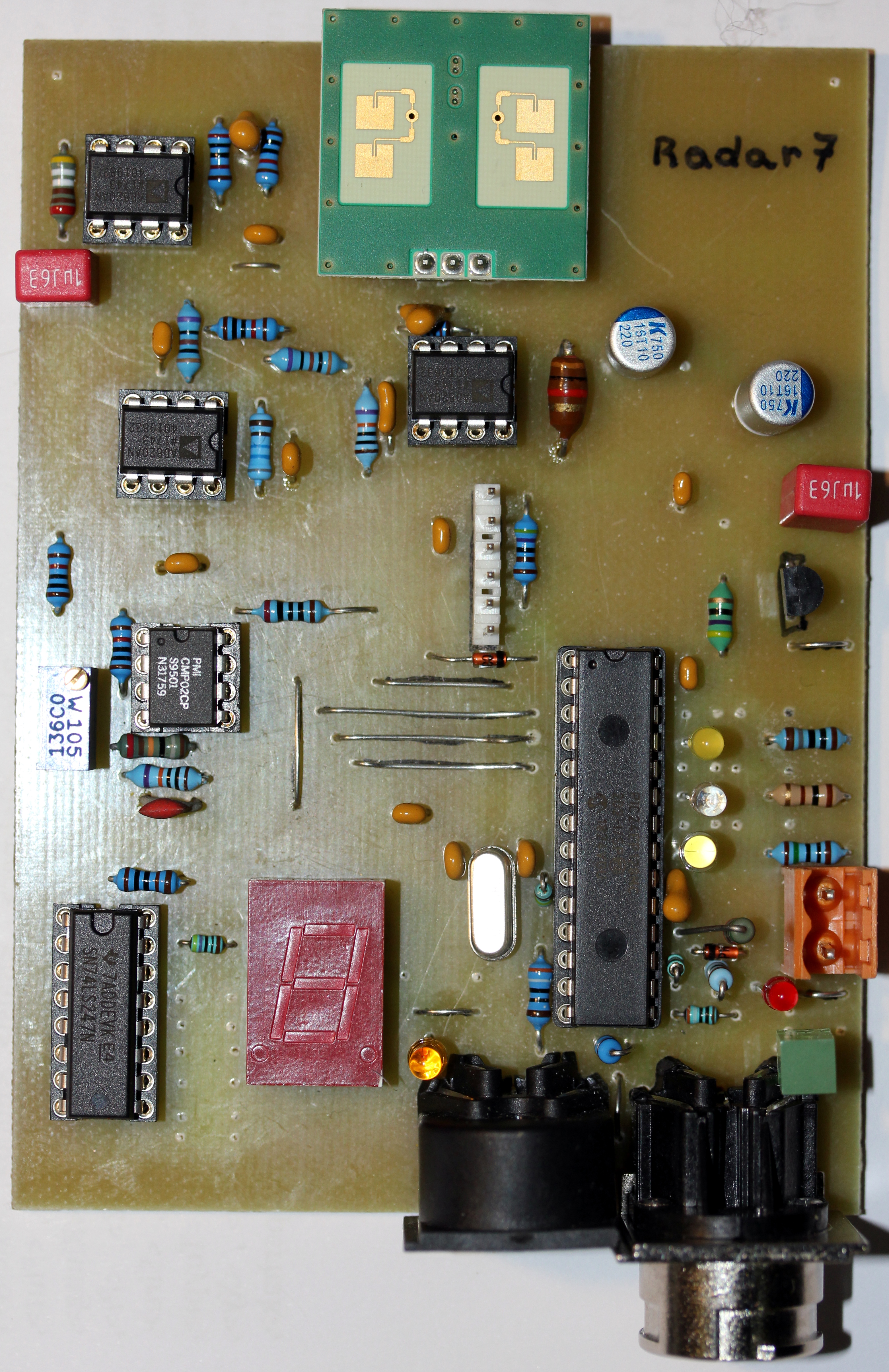 Een
tweede identiek board zou wenselijk zijn, gezien de grootte van deze robot.
Hans Roels suggereert de toevoeging van een heus motorgeluid. Een kleine via
een elektromotor aangedreven zuigerkompressor misschien? Een krachtige propellor?
Met zo'n kleine zuigerkompressor kunnen we zelfs een grote scheepshoorn aansturen
en toevoegen. Ventielen hebben we ook nog op voorraad. De kompressor heeft een
universeelmotor met een werkspanning van 230 V. Het opgenomen vermogen is 165
Watt. Voor de aansturing kunnen we verder werken vanuit de ontwerpen en experimenten
uitgevoerd bij de konstruktie van de <Balsi> robot.
Een
tweede identiek board zou wenselijk zijn, gezien de grootte van deze robot.
Hans Roels suggereert de toevoeging van een heus motorgeluid. Een kleine via
een elektromotor aangedreven zuigerkompressor misschien? Een krachtige propellor?
Met zo'n kleine zuigerkompressor kunnen we zelfs een grote scheepshoorn aansturen
en toevoegen. Ventielen hebben we ook nog op voorraad. De kompressor heeft een
universeelmotor met een werkspanning van 230 V. Het opgenomen vermogen is 165
Watt. Voor de aansturing kunnen we verder werken vanuit de ontwerpen en experimenten
uitgevoerd bij de konstruktie van de <Balsi> robot.
07.06.2023: De kompressor wordt ingebouwd:
Hier is het merknaamplaatje: 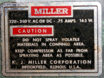 Uitgaan van het ontwerp van <Balsi> is een optie, maar ook een triac motorbesturing
is hier te overwegen. Da's heel wat goedkoper en voor de noodzakelijke galvanische
scheiding kunnen we een optor gebruiken. De basisplaat van de kompressor dienden
we wat te fatsoeneren en de montage op een polykarbonaat drager vergde behoorlijk
wat handigheid, om niet te zeggen dat het heel erg moeilijk was... Ook de scheepshoorn
wordt op de drager van de kompressor vastgemaakt. Een elektrisch bestuurbaar
ventiel hebben we allicht nog wel in voorraad. Als besturingsboard, komt het
tweede ex-sire board dat we nog liggen hebben, in aanmerking. Dat geeft dan
meteen ruimte voor nog wat extra lichteffecten en enkele (kleine) geluidsbronnen.
Uitgaan van het ontwerp van <Balsi> is een optie, maar ook een triac motorbesturing
is hier te overwegen. Da's heel wat goedkoper en voor de noodzakelijke galvanische
scheiding kunnen we een optor gebruiken. De basisplaat van de kompressor dienden
we wat te fatsoeneren en de montage op een polykarbonaat drager vergde behoorlijk
wat handigheid, om niet te zeggen dat het heel erg moeilijk was... Ook de scheepshoorn
wordt op de drager van de kompressor vastgemaakt. Een elektrisch bestuurbaar
ventiel hebben we allicht nog wel in voorraad. Als besturingsboard, komt het
tweede ex-sire board dat we nog liggen hebben, in aanmerking. Dat geeft dan
meteen ruimte voor nog wat extra lichteffecten en enkele (kleine) geluidsbronnen.
08.06.2023: Ontwerp motorbesturing voor de kleine kompressor. Een triac-regeling
met optocoupler lijkt hier aangewezen.
09.06.2023: Bezoek van de Deutsche Oper Berlin met interview en fotoshoot.
11.06.2023: Tweede PCB voor een radar geetst, geboord en grotendeels bestukt
en gesoldeerd.
12.06.2023: Triac modules geleverd door Farnell. Eerste tests: wanneer we de
potmeter (220kOhm nominaal) vevangen door een LDR, werkt het nog steeds vrij
goed. Een Silonex optor is dus zeker te overwegen hier.
13.06.2023: Verdere experimenten en metingen met de triac modules. Heeft het
zin de output gelijk te richten en af te vlakken teneinde de thyristor/triac
stroring te onderdukken?
14.06.2023: Die laatste vraag moet negatief beantwoord worden. Over de afvlakkondensator
zal immers ten allen tijde de volle gelijkgerichte netspanning staan. Deze Britse
triac module blijkt toch bruikbaar: 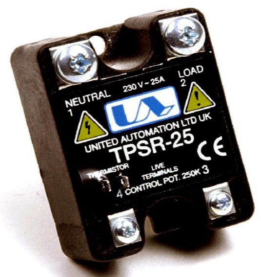 De
interne schakeling zal allicht wel zoiets zijn:
De
interne schakeling zal allicht wel zoiets zijn:  In
elk geval is er geen galvanische scheiding tussen potmeter en netspanningselektronika
toegepast. Wellicht ontbreekt ook een HF ontstoring. Wanneer we de potmeter
vervangen door een Silonex
KSL-32SR2 optocoupler, dan kunnen we een behoorlijk regelbereik krijgen
wanneer we de stroom door de LED tot hooguit 1 mA beperken. Het gegevensblad
bij de TPSR-25 geeft volstrekt geen informatie over het type thermistor dat
hierbij gebruikt moet worden. Maar, zonder zo'n thermistor blijkt de module
gewoon en normaal te werken... Als we zo'n aanpak later willen verbeteren zou
dit schema -geplukt van het internet- wellicht een goed uitgangspunt kunnen
zijn. Er moet dan wel een PCB voor ontworpen worden.
In
elk geval is er geen galvanische scheiding tussen potmeter en netspanningselektronika
toegepast. Wellicht ontbreekt ook een HF ontstoring. Wanneer we de potmeter
vervangen door een Silonex
KSL-32SR2 optocoupler, dan kunnen we een behoorlijk regelbereik krijgen
wanneer we de stroom door de LED tot hooguit 1 mA beperken. Het gegevensblad
bij de TPSR-25 geeft volstrekt geen informatie over het type thermistor dat
hierbij gebruikt moet worden. Maar, zonder zo'n thermistor blijkt de module
gewoon en normaal te werken... Als we zo'n aanpak later willen verbeteren zou
dit schema -geplukt van het internet- wellicht een goed uitgangspunt kunnen
zijn. Er moet dan wel een PCB voor ontworpen worden. 
04.07.2023: Werk aan <Rumo> terug aangevat. Firmware voor het tweede sire
board is min of meer klaar nu. Ook voerden we een patch uit op het board zodat
dit nu ook over een ICD programmeerkonnektor beschikt. We kleefden een 6-polige
header op het board met epoxy lijm.
11.08.2023: China hooters besteld in mei, geleverd. Aangezien ze met een DC
motortje blijken te werken, zijn ze prima geschikt voor aansturing met PWM.
12.08.2023: Zoektocht naar plaatsingsmogelijkheden voor de chinese hooters.
Ze blijken heel wat groter te zijn dan wat we in gfedachten hadden. Ook hun
stroomopname ( 3 A) is groter dan wat we met de L298 chips kunnen halen. Parallelschakeling
van uitgangen ( en ingangen...) is wellicht een mogelijke oplossing. Daarvoor
zijn wel heel wat 'patches' op het PCB nodig.
Maintenance information:
<Rumo> module - preliminary information
assignment of functionalities to processor boards and pins
| item | operating voltage | board | pic pins | midi map | |
| spring horn 1 Grundig | 24V - 460 mA (30V ok) | hub board | RA | note-velo | 24 |
| spring horn 2 Grundig | 24V - 460mA, > 12V | hub board | RC0 | note-velo | 25 |
| spring horn 3, deursluiter | 24V - 700mA, >7V | hub board | RC3 | note-velo | 26 |
| rasptoeter | 24V | hub board | RC4 | note-velo - slow pwm | 27 |
| brandalarmbel | 24V | hub board | RC5 | note-velo | 40 |
| on/off relay | 5V | hub board | on/off ctrl.66 | ctrl 66 | |
| DC motor bingo | 24 V - 600 mA | hub board | RC1 | pwm | 107 |
| DDR Buzzer | 24 V - 800 mA | hub board | RC2 | pwm | 37 |
| Red rotating light | 240V ac | hub board | RA1 | via opto relais | 126 |
| Nestor Martin coffee burner | 24 V | special motor board |
pwm |
108 | |
| Clay bells - motor | 15V / 24V | clay-bell motor board | pwm HPWM1 | 105 | |
| Green LED strip | 24V | Clay bell motor board | velo= flashing speed | 121 | |
| Green LED strip | 24V | Clay bell motor board | 122 | ||
| Green LED strip | 24V | Clay bell motor board | 123 | ||
| Whisper 1 - 8 | 12/17 V | whisper 2 board | 8 x pwm: velo | 96-103 | |
| 2 shakers | 12/17V | whisper 2 board | note-velo | 94-95 | |
| brass post horn ABT buzzer B | 12V | 3-channel synth board | 26,25 |
note-velo-adsr |
59, 71, 83, 86 |
| dual horn - ABT buzzer F# | 6V [12V] | 3-channel synth board | 24,23 |
note-velo-adsr |
66, 78, 85, 90 |
| brass horn ABT buzzer A | 12 V | 3-channel synth board | 22,21 |
note-velo-adsr |
69, 81, 88, 93 |
| Theban Bb trumpet | 16 Ohm Boyer driver | 3-channel motor board | 26,25 | note-velo-adsr controllers |
46, 58, 65, 70, 73, 80 |
| hooter 1 D | 16 Ohm driver | 3-channel motor board | 24,23 | note-velo-adsr controllers |
50, 62, 69, 74, 77, 79 |
| hooter 2 E | 8 Ohm driver | 3-channel motor board | 22,21 | note-velo-adsr controllers |
52. 64, 76, 82, 89, 84 |
| claxon horn 1 | 12 V -1.2 A | sire board - pwm | pwm | 33 | |
| claxon horn 2 | 12 V -1.2 A | sire board - pwm | pwm | 34 | |
| claxon horn 3 | 12 V -1.2 A | sire board - pwm | pwm | 35 | |
| claxon horn 4 | 12 V -1.2 A | sire board - pwm | pwm | 38 | |
| buzzer | 12-14 V | sire board - pwm. needs capacitor! | pwm | 47 | |
| shaker | 12 V | sire board - note/velo | note-velo with autorepeats | 39 | |
| Gnawa clapper 1 | 24 V | sire board - note/velo | note-velo with autorepeats | 41 | |
| Gnawa clapper 2 | 24 V | sire board - note/velo | note-velo with autorepeats | 42 | |
| orange rotating light | 12-24 V | sire board - on/off | on/off only | 127 | |
| Red LED strip left | 12 V | sire board - pwm | pwm | 125 | |
| Red LED strip right | 12 V | sire board - pwm | pwm | 124 | |
| Miller air compressor | 220-240 V - ac/dc | sire2 board - pwm | pwm | 28 | |
| ship horn | 24 V | sire2 board - pwm | pwm | 29 | |
| escape valve | 24 V | sire2 board - pwm | pwm | ||
| Tungsten light | 24 V | sire2 board - pwm | 120 | ||
| ABT-047-RC buzzer | |||||
| Siemens motor | 24V 40mA | ||||
| Vintage Horn 1 | 12 V / 3A | sire2 board - pwm | pwm | 31 | |
| Vintage Horn 2 | 12 V / 3A | sire2 board - pwm | pwm | 32 |
Electromagnets used for the two springs with acoustical membrane amplifiers: Grundig Radio Werke Gmbh, Relaismagnet 38/33. DC resistance: 55 Ohm. These components were taken from relays. They have a laminated core and thus can even be operated with AC..
Tubular solenoids used for the Gnawa clappers: Emessem, 24V (@100% dc), 104 Ohms.
Fans used for the whisper components: Sanyo 9GA0412P6G001 (these are variable speed PWM types!)
Crouzet motor power supply: Traco Power TMM60124, Farnell part nr. 2451695. Specs.: Medical, 24V - 2.5A. [used for the coffee roaster component]
Crouzet DC motor (for Nestor Martin coffee grinder)
Bingo/Lotto trommel: Longfield Games
Doga motor (made in Catalunia): Motor 111 RH 24V 1SP W/EMC W/O P W/O TH. Production date: 08.03.2022, RS-order nr.: 380-8649
Transducer ABT-416-RC
Induktie is 7.5mH bij 100 Hz, 7.6mH bij 120 Hz, 7 mH bij 1kHz en 4.47 mH bij
10kHz. (Meting met LCR meter 1703, RS-pro, 01.11.2022) (gebruikt voor de dubbelhoorn,
noot 66 en de klakson, noot 69)
Transducer ABT 414-RC (gebruikt in de posthoorn, noot 59)
Buzzer: MoFlash, type AE30M-FT-01, fres = 450 Hz, 14V dc - 30mA. Requires a 220nF cap in order to work with PWM.
Traco power module TMPM 04112, 12V - 0.3A. Farnell order number 208-0707
(On 3-channel synth board)
<Hunt> module [no longer documented here. For
current documentation use this link.
Belimo
LM24 motor. [used for the hunting horn component]
Relay's on the Belimo motor control board: Haller-Relais,
HB8-4-1B8-702, Spule 12V dc, kontakte: 28V dc or 115V ac, max. 30W.
Penny+Giles
tilt sensor [on the hunting horn assembly]
Green LED strips: Farnell order nr. 2214012. Total power = 14.4 W. There are 10 section of each 6 SMD LED's. So, each section draws 1.44 W and each individual LED 240mW. In current terms: the full length draws 600mA, one section 60mA and each LED 10mA. The adhesive strip unfortunately is not isolated and thus can not be sticked to a conductive surface...
Orange rotating flashlight: 12/24V, Current drawn (as measured): 120mA @ 24V, 240mA @ 12V. In rumo this light is powered from the 24V supply.
Red rotating flashlight: Telemecanique, XVR-1M04 , 230V ac, original bulb 25W ba15d socket, replaced with 40W bulb: Halolux JD 40W, ba15d.
Red LED bar lights: 12V per unit, two by two connected in series. Production date: 2010.
XP-Power SMPS power supply 24V - 6.5A.
Dual power supply for the synth2 board: 2 x XP-Power model VET24US120C2-JA. Input: 100-240V AC, output 12V - 2A. Connected in series. Watch out: the -12V is at ground and the center 0V should not be grounded!!!
48V - 2A SMPS power supply: XP-Power type VCS100US48. Input: 100-140V ac, output 48V, 2.08A.
Air compressor: K.J. Miller Corporation, Brookfield, Illinois, USA. 220-240 V dc or ac, 0.75 A, 165 W.
Antique horns: Horn Type R, DC 12V, Article nr. 606. OO-GA! OO-GA! Sound, 12VB/3A, SPL 110 dBA, f= 490Hz. Made in China, ordered via Banggood.
 (This is at 200%.Real size of the PCB is 80 x 100 mm, half Euro-card)
 This
was removed from the <Rumo> project and found a final destinalion in
the <Hunt> robot.
Unstabilised output voltage: 17V
The PCB for this circuit (at 200%) looks like this:
This
was removed from the <Rumo> project and found a final destinalion in
the <Hunt> robot.
Unstabilised output voltage: 17V
The PCB for this circuit (at 200%) looks like this:  The
source code for this board is here.
And this is the PCB:
The
source code for this board is here.
And this is the PCB: 
 The PCB for this circuit (4 times on a single PCB):
  The finished board looks like this:
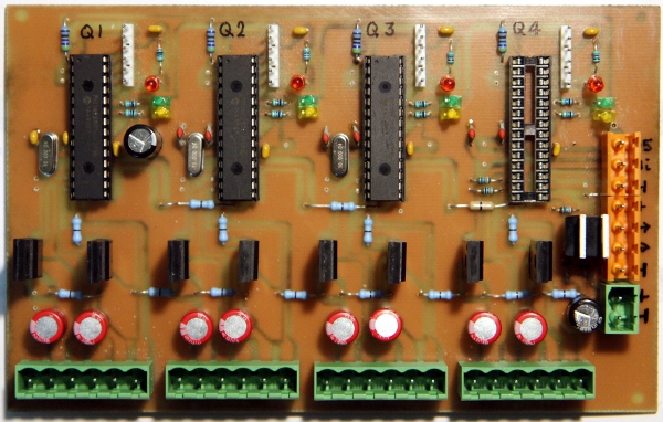
Circuit for the 2-channel audio amp:
As of 16.05.2023, not sure that we will use this in <Rumo>.
Circuit for the four claxons, the gnawa clappers and the red/orange lights:
wiring diagram for this circuit:
As this board does not have an ICD connector, we made an IC clip for programming:
Boards used to make the robot fully interactive:
Radar7 board:  And the circuit drawing for this board:
  The realised and populated board looks like this:
The board for radar 8 is nearly identical to this one. Only the firmware is
very different.
The realised and populated board looks like this:
The board for radar 8 is nearly identical to this one. Only the firmware is
very different.
Overview of all circuits active in the <Rumo> robot:
References: