<BalMec> |
|
<Prop1>, <Prop2>, <Prop3> :three remote controlled large airplane propellers <Bello>: remote controlled industrial electric bells for Ballet Mecanique , George
Antheil by Godfried-Willem Raes in part commissioned
by the Ictus ensemble 2014-2017 |
George Antheil (08.07.1900 - 12.02.1959) was a great admiror of the futurists ideas. Hence he introduced quite a variety of industrial noises in his orchestral music. The ballet mecanique, a ballet for machines, prescribes no less than three airplane propellers on stage together with a battery of seven industrial electric bells, some 16 player pianos, a siren and percussion. It was written between 1923 and 1924. All too often, orchestras performing this music fake these essential components either by subsituting them with percussion instruments, or even worse, by sampled sounds reproduced on loudspeaker channels. Needless to say that this goes against the composers original intentions, although during his entire lifetime he never got these components working as conceived. Just like Igor Strawinsky in his original version of Les Noces, he even never got the player piano's to play in sync... Nowadays it ought to become possible to realize all those ancient dreams, even though the composer during his lifetime has compromised his own ideas on many occasions. In some performances of the Ballet, large fans have been used and -as these devices are pretty noiseless- the composer had the players hold sticks against the blades... This clearly doesn't lead to anything like an airplane sound However, having working real airplane propellers on stage was and still is, not a trivial undertaking. The construction of these elements, such that they can safely be used in performances, was confined to us as a collaborative project with the Ictus ensemble.
Propellers:
We started off by tracing suitable real airplane propellers -not fan blades- and studying the mathematics and physics of their behavior, as obviously having them rotate at the normal speed as on an airplane would entail very high thrust forces to be developed. Prohibitively dangerous. Hence we designed the motors such that all forces developed are in a safe range. Also we designed the structures such that they produced blowing wind, instead of sucking wind as in aircraft. Doing so, the forces are always developped backwards. The artistic problem is that at too low speeds, the propellers do not make the airplane noise requested and wanted by the composer. This lead us into researching the shaping of the blades such as to make them produce more noise. Another research topic was to consider the possibility to let the fan blades closely cross the edge of low pitched resonator tubes, thus provoking the typical low frequency noise of an aircraft propeller. This also makes possible the rhythmic notation used in the score. On propeller 1 such a resonator was build. The result is very convincing. A similar design on the large propellers was impractical as the resonators would become physically to large. Maybe Helmholtz resonators could be applied here.
Propeller 1:
This is a rather small propeller, span 660 mm (26"), carved from wood. The motor used here is a DC motor, making precise control relatively easy. The motor rotation is transmitted to the propeller axle with a V-belt. The gear ratio can be changed by mounting different pulleys. An adaptor piece was turned on the lathe to make the propellers central hole fit the axle. This was fabricated from a piece of nylon, outer diameter 30.0 mm, inner diameter 14.5 mm, length 45 mm. The propeller axle is mounted on a steel holder made from a piece of HEA 100 x 100 profile. The axle is mounted on this part with four M10 x 35 bolts. The motor base -in construction steel as well- is cut out from a 450 mm long piece of 100 x 50 x 4 rectangular profile, also serving as a resonator. At the back end of this tubing, we constructed an acoustic horn to amplify the sound in the 80Hz to 130Hz range. The horn is folded, with the opening pointing to the audience. This yields a quite convincing airplane sound, although below the sound pressure level of a real prop-engine.The motor power was calculated to stay below 10% of the nominal power required for use on an airplane (estimated at some 5 to 8 kW). The whole structure was firmly welded together.
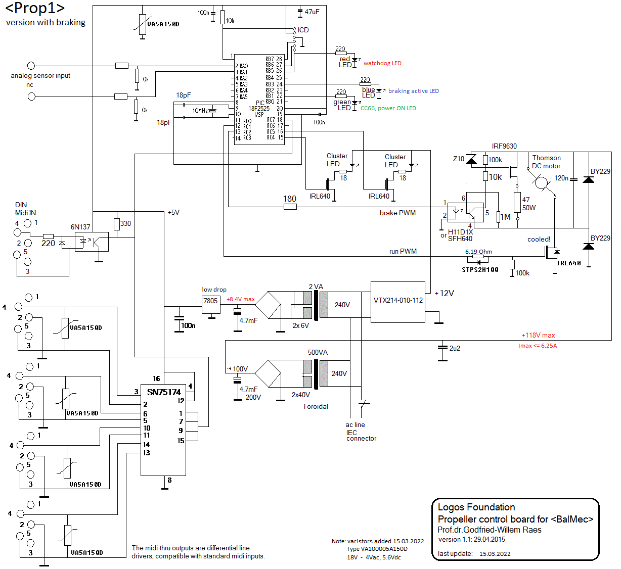
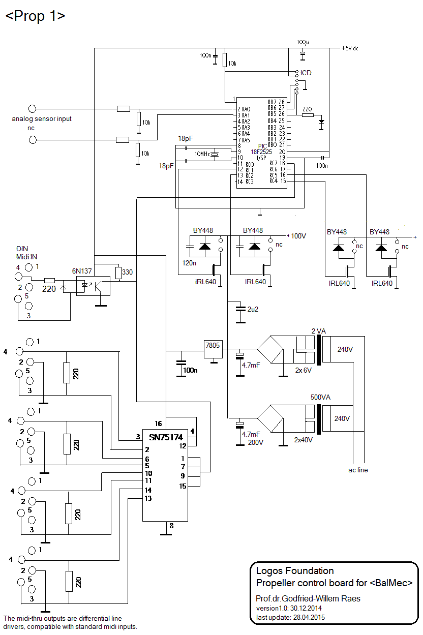
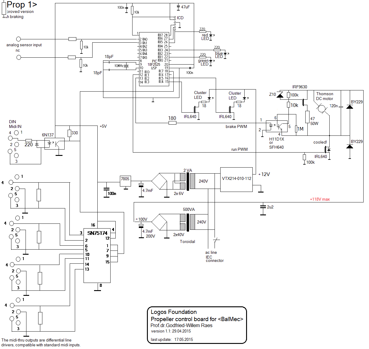
The electric control of the propeller is not as easy as it might seem. As long as we only have to cope with very slow changes of rotation speed, we can live with just variable voltage control on the motor. However, if we want relatively fast braking, we have to deal with the problem that the motor -due to the inertia of the propeller- will become generative. This imposes the use of braking resistors and precise electronic control. Hence the PIC microprocessor (an 18F2525) needs two PWM controlled output channels: one for speed control, one for braking. Also the analog input channels can be used to monitor motor -and thus propeller- behaviour at all times. This is the circuit we designed for the MIDI control of the propeller:
As we anticipate that in practical use, the distance between the different components of the setup might become relatively large, possibly exceeding the 5 to 10 meter limit for MIDI cabling, we provided in differential line drivers on all MIDI boards. With these, cables up to 100 meter in length can be used. For reliable performance, screened twisted pair cable should be used. DMX cable, properly terminated works very well.The firmware for the 18F2525 microprocessor can be found here: Propeller1.bas
Midi implementation:
- Channel 13
- The propeller is mapped on note 40
- Note-off stops the propeller. The release byte controlls the braking force.
- Note-on with velo = 0 turns the propeller off without braking.
- Note-on with velo> 0 makes the propeller rotate at a speed proportional to the velocity value.
- Notes 120 and 121 are mapped on red LED spot lights, flashing speed being a function of the velocity byte. Flashing speed can be controlled with the key pressure command.
- Controller 66: enables (>0) or disables (=0) propeller operations
- Controller 123: all notes off, stops the propeller, stops the lights.
Warning:
This machine is potentially very dangerous. It should be set up at least 1.5 meters above where people can be. Make sure there are no loose objects behind the propeller as it would suck them forward. The wind production of this machine can be considerable. When not in use, the machine should be fully switched off with a remote switch. We did mount a switch on the machine but using this for turning off the propeller involves a serious danger for the operator. Also we assume no responsibility for accidents as a result of using the machine with other midi sequences than those we provide.
Propeller 2:
This propeller is also made of wood, but coated with polyester and carefully balanced in the Hofman propeller factory. The wind span is 1890 mm. Size of the axle mounting hole: 58 mm, provisions made for flange mounting with 6 M12 bolts.
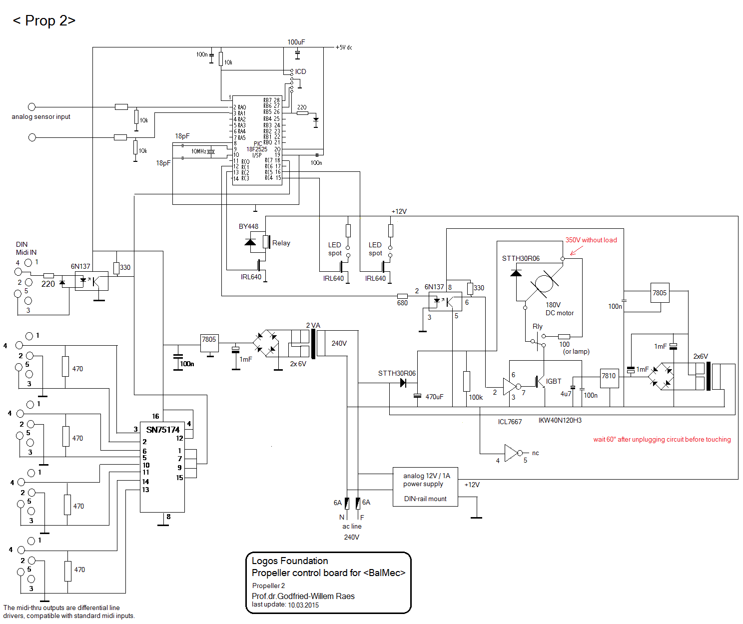
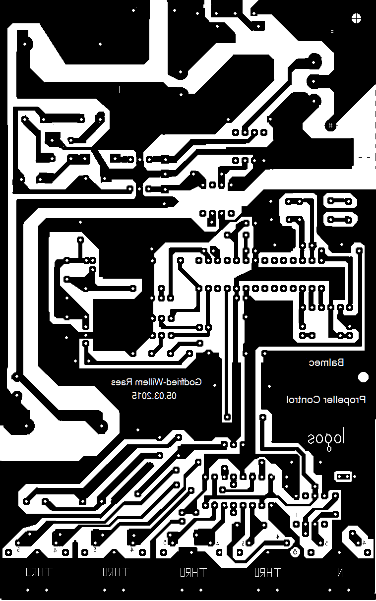
The motor used to drive it is a GPM90, 0.75kW DC motor designed for 180 V DC operation at 1500 rpm. This motor is powered from the mains single side rectified voltage directly. This is the circuit for the control:And, this the PCB for the above circuit. As we did not find enough space on the board to accomodate a 2.2mF / 450V electrolytic as originally foreseen in the schematic, we mounted a 470uF/400V type. If a larger value is required it will have to be added off-board. The motor brake relay as well as the braking resistor (or light bulb) should be mounted on the motor itself. As parts of the PCB are directly coupled to the mains voltage a word of warning may not be misplaced here: this board does carry high voltages! Do not touch. There is galvanic isolation between input and output, so using the circuit involves no danger. The steel structure itself is properly grounded.There are two automatic fuses on the machine making it possible to cut all power, however these fuses should not be used as a switch taking into account that being in such close proximity to the propeller entails a danger in its own, For safety reasons we advise users to use a switch in the power wire at least 5 meters away from the engine.
The motor for this propeller is a flanged type, so it was a lot of work to construct a well fitting flange to fit the motor on the HEA220 profile base. The center hole has to be 130 mm diameter and the M12 mounting bolts have to be countersunk types.
When braking, the motor becomes a generator. To make reasonably fast braking possible we provided a braking resistor switched over the motor windings on a stop command. In fact this resistor is a 205 W halogen bulb (Osram). The normal resistance would be 258 Ohms, but when cold this value is down to 25 Ohms. It is absolutely normal that this lamp will never glow in this application.
These are pictures of the left and right side of the circuitry for propeller 2:
The firmware for the PIC microprocessor can be found here.
Midi implementation:
- Channel 13
- The propeller is mapped on note 38
- Note-off with a release value makes the release value control the braking force.
- Note-on with velo = 0 turns the propeller off and uses default braking
- Note-on with velo> 0 makes the propeller rotate at a speed proportional to the velo value.
- The two red lights are mapped op notes 122 and 123. The velocity byte steers the flashing speed.
- Controller 66: enables (>0) or disables (=0) propeller operations
- Controller 123: all notes off, stops the propeller.
Warning:
This machine is potentially very dangerous. It should be set up at least 2 meters above where people can be and securely bolted or clamped to the holding structure. Make sure there are no loose objects behind the propeller as it would suck them forward. The wind production of this machine can be considerable. When not in use, the machine should be fully switched off with a remote switch. We did not mount a switch on the machine as doing so would involve a serious danger for the operator. Also we assume no responsibility for accidents as a result of using the machine with other midi sequences than those we provide.
Propeller 3:
This is a heavy duty propellor made in metal, presumably a magnesium-aluminium-titanium alloy. The wing span is 1740 mm and the axle hole is 58 mm. As on propeller 2, it is also designed to be mounted on a six hole flange.
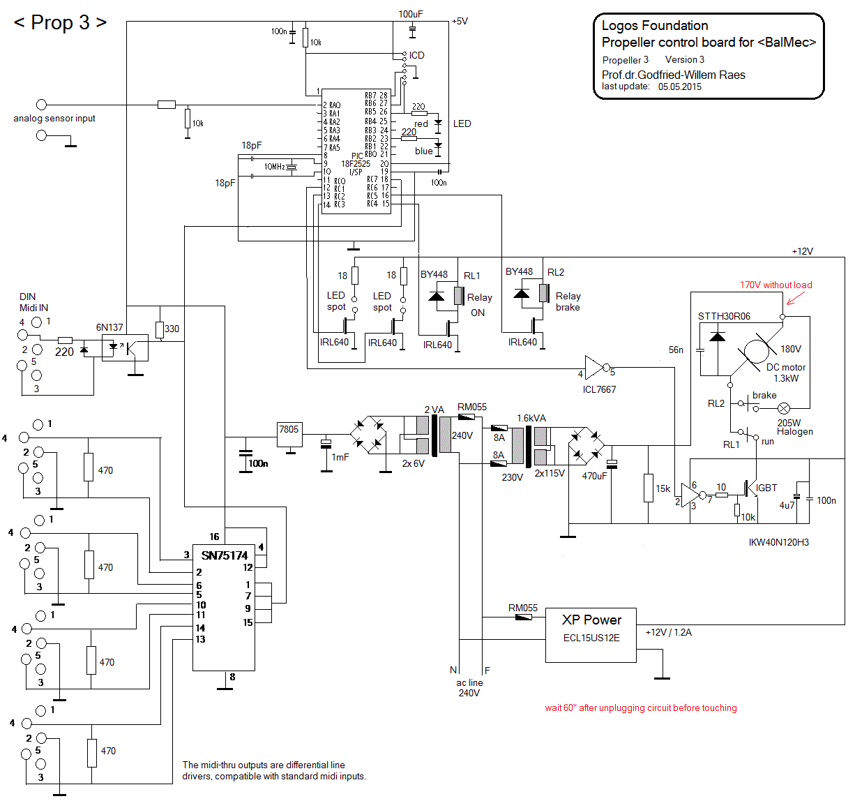
The motor used to drive it is a GPM90, 1.3kW DC motor designed for 180 V DC operation at 1500 rpm. The circuit for the control is almost identical to the circuit used for propeller 2, but here we used a separation transformer avoiding the trouble we had with a first version using single side rectified mains voltage directly. Thus many improvements were added to the PCB design as well..This is the circuit drawing:
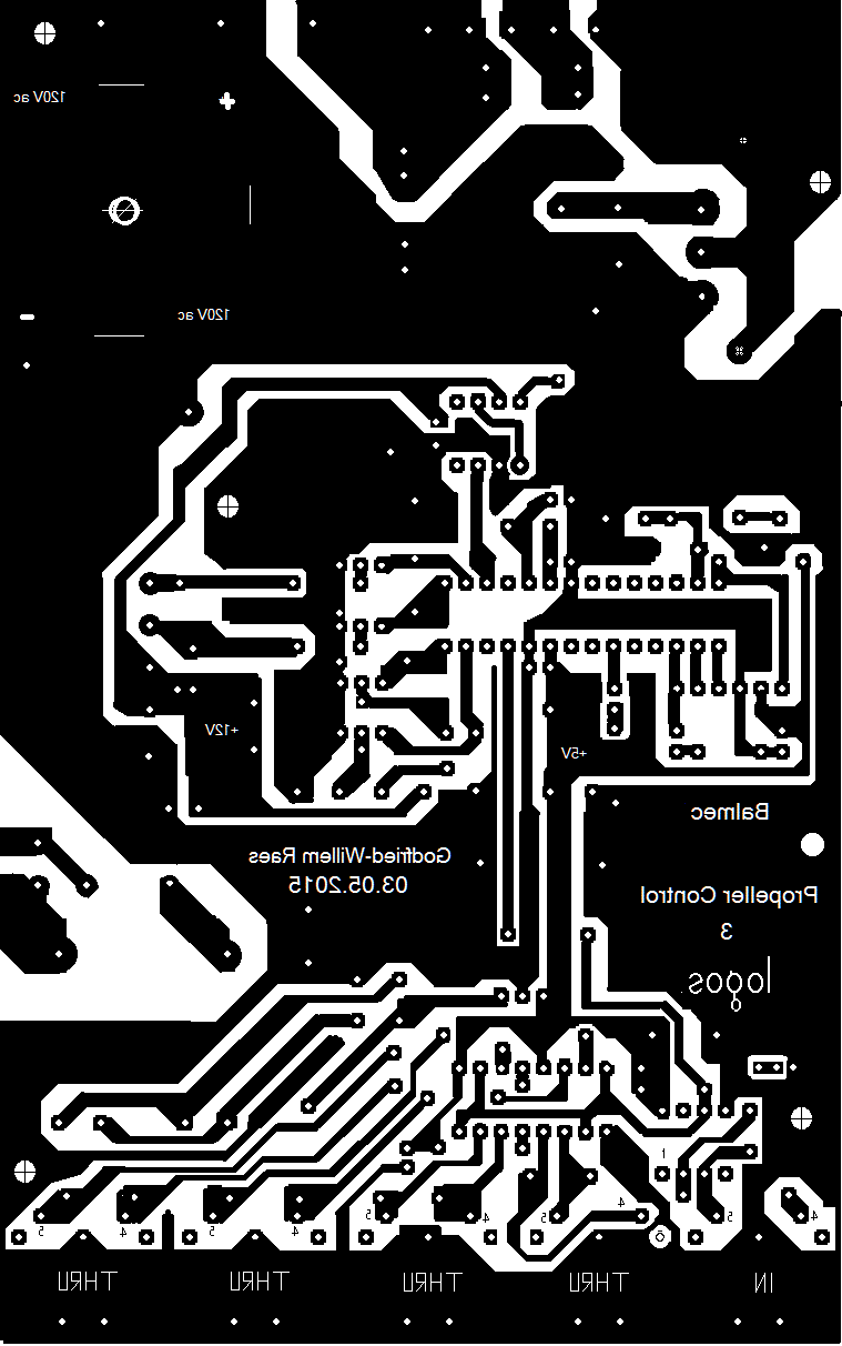
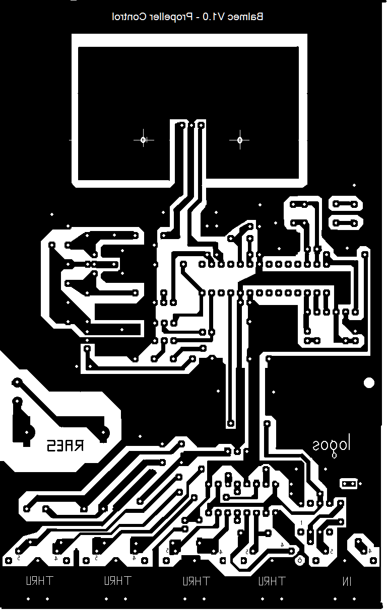
And, the version 3 PCB design looks like this:
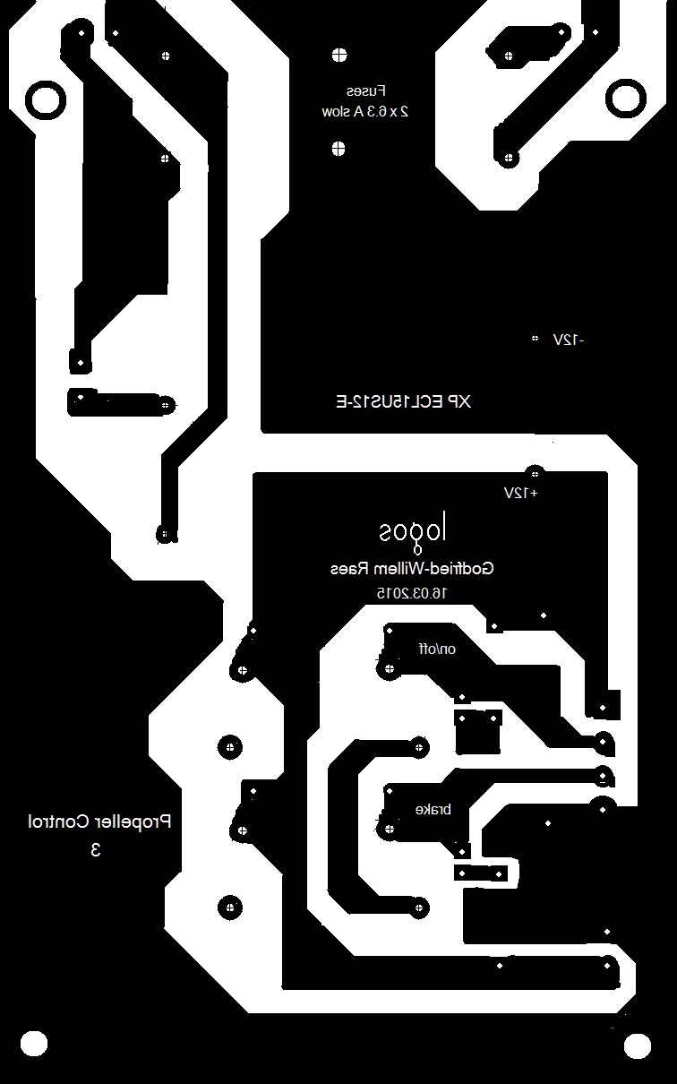
The power relays, the fuse holder and the SMPS 12V power supply found a place on another printed circuit board: Making this board made final wiring a lot more transparant than was the case for propeller 2.
These are pictures of the left and right side of the circuitry for propeller3:
As it is the case with the notation in the score for the siren, it is unclear at what speed the propellers are supposed to sound. It is technically impossible to start/stop propellers fast. We found a solution by providing a switchable resonator for the propellers that can switched on very fast. Thus it would no longer be required to have the propellers themselves to change speed rapidly. As yet, this feature is under study.
The firmware for the PIC microcontroller can be found here.
Midi implementation:
- Channel 13
- The propeller is mapped on note 36
- Note-off with a release value makes the release value control the braking force.
- Note-on with velo = 0 turns the propeller off and uses default braking
- Note-on with velo> 0 makes the propeller rotate at a speed proportional to the velo value.
- The two red lights in front are mapped on notes 124 and 125, the velocity byte steers the flashing speed.
- Controller 66: enables (>0) or disables (=0) propeller operations
- Controller 123: all notes off, stops the propeller.
Technical specifications:
- Power: 1.6kW, 230V ac
- Weight: 83 kg
- Size:
- 1 Midi input
- 5 differential midi outputs (thru's) capable of driving very long DMX cables.
- Insurance value (construction cost): 6691 Euro.
Warning:
This machine is potentially very dangerous. It should be set up at least 2 meters above where people can be and securely bolted or clamped to the holding structure. Make sure there are no loose objects behind the propeller as it would suck them forward. The wind production of this machine can be considerable. When not in use, the machine should be fully switched off with a remote switch. We did not mount a switch on the machine as doing so would involve a serious danger for the operator. Also we assume no responsibility for accidents as a result of using the machine with other midi sequences than those we provide.
Electric bells <Bello>:
See separate page with details on this robot.
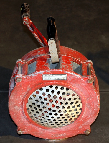
<Balsi>: Large motor driven siren
The instructions in the score render it impossible to use a standard crank driven siren, as it is detrimental to the gears in these devices to be started and stopped fast. So an electrically driven mechanical siren with safe braking possibilities or fast sound control has to be designed. The score is very unclear as to the pitches the sirens are supposed to sound. In the score they appear notated as percussion instruments. We made already a few siren driven robots: <Sire> , a robot using 24 small sirens as well as the large siren integrated in <Springers>.
The documentation for <Balsi> is on a separate webpage. Click here.
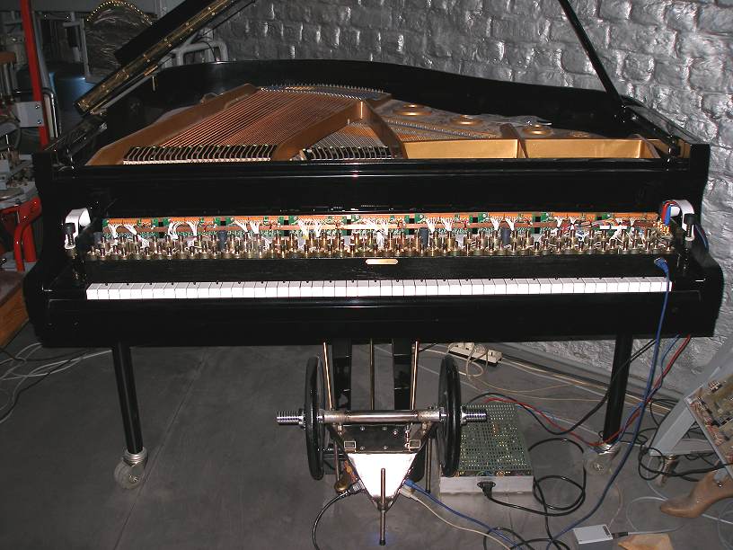
Player Pianos:The original score requires 16 player piano's, although there are only four autonomous tracks. The reason behind this, is that on traditional piano rolls, it is impossible to have that amount of notes as the paper would fall into pieces. Obviously electrically driven automated pianos do not have this restriction making performances using just 4 player pianos perfectly possible. All performances so far if using player pianos (and not sample-based midi keyboards with their uggly sound...) at all, suffered from the problems associated with commercially available midi controlled pianos: latency (500ms), lack of polyphony, weak dynamic possibilities. This is the case for the Yamaha Disklavier, the Q&R vorsetzers etc... The player pianos as we designed and build do not have any of these problems. Detailed descriptions and comments on our Player Piano's can be found on this website. The only problem is that at the time of this writing (2015) we made only two copies. So either we have to make two more vorsetzers, or rearrange the score to get it played on the two pianos we already have.
Musicians parts:
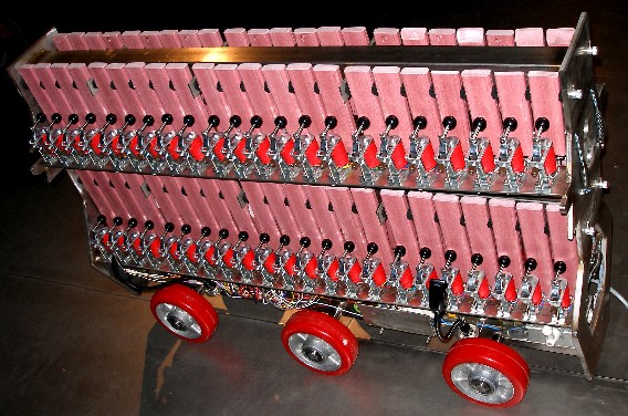
The score calls furthermore for three xylophones, two grand pianos, a tamtam, four bass drums. It is perfectly possible to also confine these parts to real musical robots. Our <Xy> robot can take care of the xylophone parts. Automating the bass drums and a tamtam would be pretty straightforward...
Midi Implementation for all components of <Balmec>
The Balmec project was conceived to work like all other musical robots we have built. Hence it makes use of one unique midi-channel and all components of the project are mapped on midi notes and controllers.
Midi channel: 13 (counting from 0) for all modules.
Note On/Off mapping:
Note 24: Siren. The maximum speed is controlled by controller #24. Note-On commands let the siren speak freely, Note-Off commands mute the siren. To stop the siren motor, controller 24 must be set to zero.
Note 36: propeller 3 (large metal propeller). The speed of rotation is controlled by the velocity byte
Note 38: propeller 2 (large wood propeller). The speed of rotation is controlled by the velocity byte
Note 40: propeller 1 (small propeller). The speed of rotation is controlled by the velocity byteNotes 51 - 93: Electric bells on <Bello>. The velocity byte steers the loudness (the force of the stroke) and repetition rate can be controlled with the key pressure command. The repetition speed set with the key pressure command is 'sticky', so users do not have to send it again for every note. The key pressure command can also be sent when no notes are playing. If the repetition rates are set high, low velocity values ought to be used.
Note 119: switch on/off the red LED bottom lights on <Bello>. The velocity steers the brightness of the light.
Notes 120 and 121 switch on/off the red LED spotlights on propeller 1. The velocity steers the speed of the flashing. Keypressure can be used to further modulate the flashing speed.
Notes 122 and 123 switch on/off the red LED spotlights on propeller 2. The velocity steers the speed of the flashing. Keypressure can be used to further modulate the flashing speed.Notes 124 and 125 switch on/off the red LED spotlights on propeller 3. The velocity steers the speed of the flashing. Keypressure can be used to further modulate the flashing speed.
Notes 126 and 127 switch on/off the red LED spotlights on <Bello>. The velocity steers the speed of the flashing. Keypressure can be used to further modulate the flashing speed.
Controller 66: Switches off all components when the data byte is zero. If a non-zero value is sent, the components are powered on. Controller 66 with value zero also resets all controllers to their default startup values.It also resets the note-repetion rates on <Bello>.
Controller 123: All notes off, without affecting any controllers nor key-pressure settings.
Prof.dr.Godfried-Willem Raes
Collaborators on this project:
- Laura Maes
- Mattias Parent
- Xavier Verhelst
- Kristof Lauwers
- Moniek Darge
- Lara Van Wynsberghe
Cost calculation:
Propeller 1:
Materials:
Thomson DC motor 700W 600 €Propeller 150 €Transportation propellers 152 €Ball beared axle, cast iron 240 €Steel profiles and plate material 80 €Welding materials 40 €Bolts and nuts 40 €V-belts QPIII XPZ 20 €MIDI control board 220 €M10 stainless steel bolts 26 €500 VA transformer 2 x 40V 135 €10000uF/200V cap 85 €Power rectifier 4 €Red copper, 1kg, nose piece 13 €Polyurethane varnish 5 €Steel plate 3mm thick 10 €ZnO steel painting 2 €Grinding and cutting disks 20 €LED spotlites 45 €sum 1887 €
Labor:
Welding and metal works 2 days 700 €Lathe works 0.5 day 175 €Painting and assembly 1 day 350 €Testing 0.5 day 175 €Circuit & PCB design 1 day 350 €Horn construction 3 days
1050 €PCB production and soldering 1 day
350 €
Firmware development and writing of testcode under GMT 1 day
350 €Final assembly 0.5 day
175 €Mounting of LED spotlites 0.5 day 175 €sum 3850 €End sum: 5737 €
TO DO:
- Mount build in MEMS microphone with preamp and XLR output plug. (To be discussed with Ictus)
Propeller 2:
Materials:
DC-Motor GPM90 0.75kW 1038 €Propeller 200 €Axle adaptor (lathe work) 273 €PCB motor control + components and microcontroller 250 €HEA220 profile 80 €Steel plate material 50 €50 mm x 50 mm x 4 mm profile (legs) ( 3 m) 70 €Bolts and nuts 40 €Grinding and cutting disks 40 €Welding materials 35 €Mains power entry plug CEE 16A/230V 20 €LED light clusters (Kingbright) 22 €18 Ohm power resistors on lugs 10 €12 V power supply 50 €Mains fuses and socket 30 €Power relays and IRF540 MOSFET 58 €Braking resistor 10 €Polycarbonate plate 90 €sum 2366 €
Labor:
Circuit & PCB design 2 days 700 €PCB production and soldering 1 day
350 €Firmware development and writing of testcode under GMT 1 day
350€Construction of the motor flange mount and cutting of the HEA220 beam 1 day 350 €Welding of the tripod, cutting of the profiles, grinding and drilling 1 day 350 €Wiring and electric mounting works 1 day 350 €Painting with Zinc-oxyde gray paint 1/2 day 175 €Final assembly, rail mount devices for safety and protection 1 day 350 €Extensive hardware debug and fixes 1 day 350 €Testing session. Final measurements and behavior evaluation. Final version of the firmware. Cutting, drilling and welding of the feet plates. 1/2 day 175 €sum 3400 €End sum: 5766 €
TO DO:
- design a Helmholtz resonator, if required.
Propeller 3:
Materials:
DC-Motor GPM90 1.3kW 1334 €Propeller 300 €Axle adaptor (lathe work) 280 €HEA220 profile 80 €50mm x 50mm x 4 profile (legs) (3 m ) 70 €Motor control board with microprocessor, Version 1.0 380 €12 mm thick steel plate, 10kg 30 €LED light clusters (Kingbright) 22 €Bulgin fuse holder with 6.3A fuses 12 €Relay and SMPS board 150 €Polycarbonate plates 90 €Version 3.0 microcontroller board 380 €Isolation transformer 1.6kW 250 €sum 3366 €
Labor:
PCB production and soldering motor control board 1 day
350 €Firmware development and writing of testcode under GMT 1 day
350 €Technical drawing for axle construction on the lathe 1/2 day 175 €Welding of the tripod, cutting of the profiles, grinding and drilling 2 days 700 €PCB design relay, fuses and 12V power board 1 day 350 €Painting with Zinc-oxyde gray paint 1/2 day 175 €Safety screens made and mounted. Polycarbonate. Wiring finished 1 day 350 €Testing session. Final measurements and behavior evaluation. Final version of the firmware. Cutting, drilling and welding of the feet plates. 1/2 day 175 €Redesign of the processor board, soldering and making of a new board, mounting of the isolation transformer 2 days 700 €sum 3325 €Endsum: 6691 €
TO DO:
- design a Helmholtz resonator, if required.
TO DO:
- find a bell to extend the range in the trebble with notes 94, 95, 96. Bells for notes 58 and 59 would also be most welcome.
- construct a flight case for <Bello>
- construction of a hefty bass drum robot
- work on a fully automated version of Ballet Mechanique, inclusing all percusion parts and the xylophone.
Parts, technical specifications and maintenance notes:
Propeller 1:
The propeller assembly should only be used or powered, bolted with 8 M10 x 30
bolt and nuts to the stand. Letting the propeller run without the stand may
let it slide over the surface, flip over and cause serious injury to people
around. Even if properly mounted on the stand, people should be made to stay
away at least 1.5 meter from the structure. In front of the propeller, a strong
wind will be produced.
Motor specifications:
Our measurements, with the motor coupled to the propeller:
Motor voltage |
Motor current |
remarks |
3.5 V |
0.6 A |
this is the minimum voltage required to cause the propeller to rotate |
6 V | 0.6 A | |
10 V | 0.78 A | |
15 V | 0.88 A | |
20 V | 1.1 A | 22 W |
24 V | 1.29 A | 31 W |
30 V | 1.6 A | 48 W, at this voltage, the propeller starts to produce airplane sound |
40 V | 2.3 A | 92 W |
50 V | 2.9 A | 145 W |
60 V | 3 A | 180 W |
80 V | 3.6 A | 288 W |
100 V | 4 A | 400 W. This should be considered the safety limit. |
The propeller, made of wood, was coated with a polyurethane varnish. This varnish, sold under the name Debethane is made by Degryse n.v., Fabrieksweg 42 zone A2, 8480 Eernegem, Flanders.( www.degryseverf.be)
V-belt:XPZ617 / 3VX252
Logbook (for all modules and components in the Balmac project):
- 01.12.2014: Discussion of the collaborative project with the people from Ictus.
15.12.2014: Start of the conceptual design.
- 16.12.2014: The three propellers traced and found by Mattias Parent came in, brought by Laura Maes
- 22.12.2014: A whole bunch of railway electric bells brought in from Infrabel by Laura Maes. These were donated to us by Infrabel. Steel cutting and lathe works for propeller 1.
- 23.12.2014: Another full day of metal work to get the propeller and the motor safely work together. Motor base designed. We leave the hole in the 100 x 50 profile open on purpose, as it may help to produce an airplane sound. Decided to make the entire assembly with propellers and bells like any other of our musical robots: midi controlled. The advantage being that we do not have to design a user interface nor control panel and that remote control using just about any commercialy available midi controller by a single musician becomes possible. For safety reasons alone, remote control seems mandatory in this project.
- 24.12.2014: Further construction work. Assortment of V-belts bought at MEA.
- 25.12.2014: Test mount of components. Decision made to let the propeller blow rather than suck, as this if more safe for users (the force vector is oriented backwards). With a motor voltage of 30 V we start to get a (too soft as yet) real airplane sound, thanks to our resonating tube. Soundwize, the direction of rotation makes no difference.
- 26.12.2014: Mechanical construction welded together, using TIG process. Start design and construction of a stand. Frontal legs finished by the end of the day. The leg angles are 60 degrees. The stand can be removed from the propeller mechanism such that transportation becomes easier, this of course at the detriment of mounting time.
- 27.12.2014: Further work on the back legs of the stand. Design of a chassis for the power supply and the electronics. Test and measurement session on motor performance and structural safety. So far, we only went up to 60 V for the motor voltage. The power supply should not exceed 100V at 5A. Current limiting should be designed in.
- 28.12.2014: Toroidal transformer (500 VA) ordered from Farnell. Propeller treated with polyurethane varnish. Nose piece in red copper turned on the lathe. Test runs with higher voltages up to 120V. The resonator tube works as predicted. It could be made longer and we could make a bell for it. Sound level produced now at 80V is 84dBA.
- 29.12.2014: Design of a horn amplifier to boost airplane sound. This could become a detachable part. Painting of the steel construction with Zinc oxyde primer paint. Further testing of the propeller: if the power voltage rises higher than 100 V, the current drawn by the motor does not rise anymore (it shows a tendency to sink) and the propeller doesn't run any faster. Apparently the maximum power deliverable by the motor is reached at that point. This is conform to what we had designed. Start making an inventary as well as some repairs on the assortment of bells we got from Infrabel.
- 30.12.2014: PCB designed for propeller 1, using a DC motor. The 500 VA transformer as well as the high voltage electrolytics came in from Farnell. Thus we can go on with the construction of the power supply. This is the circuit drawing:
- 31.12.2014: Start construction of the folded horn. It involves an awfull lot of welding work. The upper surface of this horn can be used to mount the electronic circuitry.
- 01.01.2015: Further grinding, steel cutting and welding on the folded horn. All using 3mm thick steel plate.
- 02.01.2015: TIG torch failure, so we had to finish the horn using electrode welding technology.
- 03.01.2015: Propeller demonstration for a group of close friends. Discussing the project with Luk Vaes.
- 05.01.2015: Lighting, developing, etching, drilling and soldering of the microcontroller board for propeller 1.
- 06.01.2015: Testing of the finished board. Development of the firmware for propeller 1: Proton compiler for the 18F2525 chip. Midi implementation worked out. Test code integrated in GMT: resources extended, libraries recompiled. All components appear integrated as a single 'Balmec' robot. New TIG torch purchased from Welda. Welding of the horn finalized. Mounting study for the horn, it's not going to be an easy welding job. Decided to mount all electronic and power supply component under the horn, rather than in the U-fold.
- 07.01.2015: Final assembly of all electronics and welding of the assembly under the horn. First tests o.k. The voltage from the power supply under no-load conditions is 120 V.
- 08.01.2015: Painting finished, using zinc-oxyde welding paint. For the inside of the horn, we need black glossy paint, maybe spray.
09.01.2015: Reality check: it indeed works under midi control. Optimum resonance is obtained with velocity 61, to improve the time required to reach this value, it's good to start the motor with velocity 127 and shortly after send the 61 value. To realize the half notes written in the score, it is advised not to switch the motor fully off, but rather let it run at a speed below the ideal resonant speed. Propeller demonstrated for a TV broadcast. Laura Maes also made a small video snippet from the working propeller and posted it on Facebook.- 13.01.2015: Propeller 1 used in the performance of Namuda Study #49a, with Dominica Eyckmans.
- 22.01.2015: Propeller demonstration for the people from Ictus
- 23.01.2015: Hunting for heavy duty DC motors for the large propellers. Mimimum power should be 1kW at 1200 rpm.
- 19.02.2015: Design of a workable siren with shutters for fast on/off control.
- 25.02.2015: Design of the frame and trolley for the bells.
- 26.02.2015: Two ordered heavy duty DC motors came in from EMR n.v. Testing and designing can continue.
- 01.03.2015: Circuit for propeller 2 and 3 calculated and drawn out. Technical drawing made for the axle adaptor. These we will have made by bvba Werkhuizen Lentz, as our lathe is not large enough.
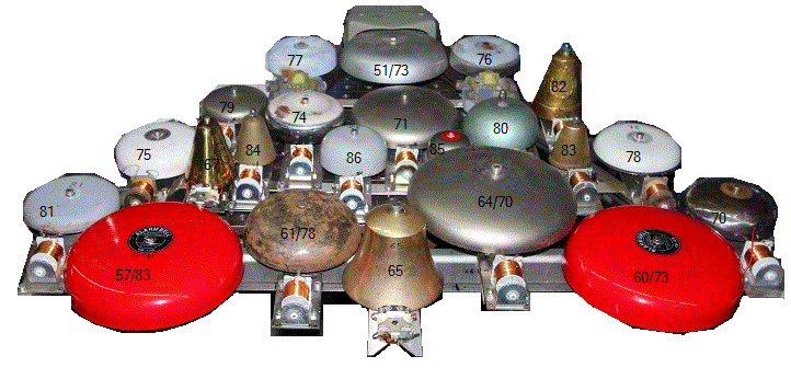
- 02.03.2015: Funke bell tuned down from 77 to 76. Friedland beel tuned down from 75 to 74. Green shell bell (note 80) mounted on a Funke mechanism. So far, bells 51, 71, 74, 75, 76, 77, 79, 80, 81 mounted. Here are some pictures for bells 75, 79 and 81: And here is a first view on the assembly so far...
- 03.03.2015: Bell for note 78 made by cutting a rim from a Friedland bell (ca. 10 mm cut off) and grinding. New note 81 bell made by cutting of a 15 mm rim from a Funke bell. The bronze bell will now have to be retuned a semitone higher to reach 82. Twelve bells mounted so far...
- 04.03.2015: Another full working day and another row of bells added. Sixteen bells mounted now. We are still looking for a solution for the notes 69, 72, 73. These are really required for Antheil. It would be nice if we could also get the pitches 64, 65, 66 and a better sounding bell for note 67. Extending in the high range is quite possible, but there is no strict musical reason to do so. Visiting the Funke and Huster site, we found out they also have bell shells with 250 mm diameter. Chances are we can tune these to our missing pitches... Let's inquire... (www.fhf.de). Also found some large shell (10", or 250 mm) fire alarm bells on Alibaba.com, in China. We ordered two of them... wait and see, or better, hear.
- 05.03.2015: Start electronic design of the board for the bell machine. Finishing the design of the control board for propeller 2, as the missing components (high voltage electrolytic caps, IGBT's, high voltage dual rectifier diodes, transformers) came in. Production of the board for propeller 2. Two boards ruined because of exhausted developper and badly working amoniumperchloride.
- 06.03.2015: Board soldering finalized. Debug and test session for the newly made propeller control board. Firmware preliminary version uploaded
- 07.03.2015: Brass handbell found on the flea market: pitch 65. Start construction of a motor holding flange for the large wood propeller. Start construction of the holding base. We use a piece of HEA 220 steel beam cut under an angle of 60 degrees. The motor comes on the flange welded on the short (400 mm) side of the beam. For mounting four countersunk M12 x 20 bolts should be used. The whole construction will be pretty heavy, but for safety reasons that's in fact a good thing. All electric and electronic components can find a place in the sides of the HEA220 profile.
- 08.03.2015: Test code for propeller 2 added to our GMT software. Firmware debug for propeller 2.
- 09.03.2015: Construction of the legs for Propeller 2. The back leg is removable (for transportability) and fixed to the base with a single M14 bolt and nut. All angles are 60 degrees. All welding of the main chassis finished now. For all larger parts, the classic arc welding technique was used.
- 10.03.2015: Two red LED cluster lights mounted on the frontside. These need a 18 Ohm series resistor to work on 12 V DC. Each of these LED clusters draws ca. 200mA. Here is the datasheet. All steel parts painted with zinc-sulphate grey paint. Drilling of the wire feed through holes through the HEA220 beam. Start wiring propeller 2. First debug session: failure, fortunately we did not mount yet the propeller, as when powering up the motor starts running at full speed with a 310V voltage across the leads... Note that the rated voltage for the motor is 180 V. There must be some bug in the hardware...
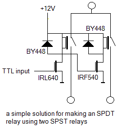
- 11.03.2015: The 5V LDO regulator found to oscilate heavily. Replacing with a regular 7805 type solved this problem. Now the ICL7667 output hangs about halfway on 5.5V with a zero volt input, thus turning the IGBT on... Some more measurements revealed the IGBT went to heaven, leaving its gate stuck to the collector. Needless to say that the ICL7667 went with it. After replacing all broken components, everything seems to work fine now. In the firmware for the PIC we will have to limit the PWM to half the possible traject as this makes the maximum voltage over the motor connections 165 Volt. Waiting for the lathe works to be finished. Tests with the propeller must wait still a bit. As it seems very hard to find SPDT relays on the market capable of switching high DC currents at high voltages, we found quite an elegant solution. When the 12V supply voltage is off, both relays will be off. It looks like a good solution for the braking circuit on the propeller motors.
- 12.03.2015: Two mounting rails placed on the HEA220 beam for placement of the mains fuses, the 12V DC power supply module, two relays, an IRF540 MOSFET and an E27 bulb socket for the high wattage halogen bulb serving here as a braking resistor. We choose an Osram 205 W halogen bulb (not seen on the picture) with a cold resistance of some 25 Ohms. It is normal by design that this lamp will never lite up. (It would in fact, if the motor were driven externally by another motor...). If we had the mounting flange for the propeller, the robot would be finished now...
- 13.03.2015: Some changes in the circuit diagram made for propeller 3, such that we have separate control over the motor-on and the brake relay. Thus the PC board for this circuit will have one more IRL640 MOSFET output. The mapping on the PIC outputs will also be very different than in the case of propeller 2.
- 14.03.2015: Cutting grinding and painting of the HEA220 profile for propeller 3. Design of a new midi-hub board for the bell-machine. Design of a relay board for propeller 3. Etching and drilling of the propeller control board.
- 15.03.2015: Welding of the two Kingbright lampholder supports for propeller 3 as well as the back leg with the M16 bolt. Drilling of mounting holes in the HEA220. Soldering of the PCB for the propeller control.
- 16.03.2015: Design and production of a PCB to hold the fuses, the two power relays and the XP 12V SMPS power supply for propeller 3. Drilling HEA220 to accomodate this board as well as the lamp socked for the brake mechanism. Testing of the motor control board.. Here is a picture of the assembled boards: Also today two ordered bells came flowing in from China: These bells have 250 mm diameter. They are designed to work on 110V ac current.
- 17.03.2015: Firmware for propeller 3 designed and first version flashed in the 18F2525 PIC processor. Start design of the 12-output pulse boards for the bell machine. Arc welding of the tripod for propeller 3. The halogen bulbs (205W) came in from Conrad as well as a bunch of Weidmueller connectors from Farnell.
- 18.03.2015: Painting of the tripod for propeller 3 with zincsulphate paint. Start mounting of components and assembly.
- 19.03.2015: Polycarbonate panels all mounted on propeller 2 and 3. Works on the bell machine - we will call it <Bello> - taken up again. Four new bells prepared. This is the bell for note 67 And this one sounds note 65: These two bells use a 24V mechanism.
- 20.03.2015: Continuing work on <Bello>. Hub board soldered.
- 21.03.2015: Welding, mounting and construction of the bottom row of large bells. Start construction of the bottom plate (10 mm thick stainless steel plate 1310 mm long, 100 mm wide): drilling of mounting holes for the side wheels, construction of an axle holder for the front and back wheels, drilling of mounting holes for the power supply transformers.
- 22.03.2015: Full day of welding and mounting works. Now the structure stands upright on its base. We added a backbone piece 30 x 50 x 3 x 1130 for stability.
- 23.03.2015: Mounting studs added for the microcontroller boards. These will be mounted on two pieces of polycarbonate plate. Bell 87 added between 86 and 64/70. This one has a stainless steel dome. Start mounting of the power supply components.
- 24.03.2015: Wiring of all power supply components on the underside of the <Bello> robot. Production of the first PCB for the <Bello> pulse board. No chance to get it working by tomorrow as we would have wished...
- 25.03.2015: Filing and honing of the axle holes to 12.00 mm. IGBT's selected for the high voltage bells: IRGB14C40, the same type we also used in our <Hat> robot in 2009. These are pin compatible with the IRL640 mosfets we normally use. The flanges for mounting the propellers came in. The flange for the wood propeller fits perfectly, the one for the metal propeller will need some further lathe work.
- 26.03.2015: Soldering work on the microprocessor board for the <Bello> robot. This work did us discover some inconveniences in the PCB design. So, we redesigned the board a bit for further production of the next two required boards.
- 27.03.2015: Funke bell caps sprayed in RAL3000 red. Propeller 2 mounted on the motor. First testing performed. High voltage double diodes ordered from Farnell. M10 x 90 bolts purchased at MEA to mount the propeller on the flange.
- 28.03.2015: Attempt to mount propeller 3 unsuccesfull. Two people required to do the job... Firmware for propeller 2 improved and uploaded. Start wiring of the <Bello> machine. Extensive testing of the firmware for propeller 3.
- 29.03.2015: Wiring on <Bello>. All wiring on the side of the already mounted bells finished. First two PCB's (hub and pulse1) mounted on the polycarbonate carrier plate. Two extra pulse boards (2 and 3) exposed, developed and etched.
- 30.03.2015: Soldering and drilling works on pulse boards 2 and 3. Board testing. Further wiring of the connectors.
- 31.03.2015: Connector wiring finished. High voltage double diodes came in from Farnell, so we soldered them on pulse board 1. Firmware for <Bello> hub board finished (version 1.0) and flashed. Propeller 3 flange needed some bore corrections, so we brough it back to the lathe workshop and had it redrilled. Propeller 3 is now fully mounted. Start coding firmware for pulse boards 1, 2 and 3 on <Bello>. This be version 1.0.
- 01.04.2015: <Bello> fired up, and indeed, it does play! Now we can check and adjust the velo scalings. During our extensive testing session two coils burned out completely: notes 77 (a Funke coil) and 82 (a Friedland coil). We have to search of a cause... Also the chinese bells (notes 57 and 60) refused service. We took them apart for close inspection and discovered that under the insulating PVC tape covering one of the coils, a diode was hidden. Also close inspection revealed a Chinese trick here: the bells are sold to operate on 110V ac, but their coils are not a pair: one coil measures 248 Ohms and the other coil only 12.6 Ohms... So clearly with a minor wiring change they can sell one and the same bell for 110V ac and for 6V to 12Vac... The weakness of the construction though is that the coils giving very unbalanced forces, cause a lot of unwanted mechanical noise... Bell 81 was not working, due to a typing error in the firmware. We started making a worksheet in order to figure out the optimum velocity scalings for the different bells.
- 02.04.2015: Friedland coil for bell 82 replaced. Construction of a new anchor mechanism for bell 77, as we didn't have replacement parts for the Funke bells. For this new mechanism we used a Black Knight solenoid rated 12V - 20 Ohms. Wiring redone as the existing wire was molten completely. Everything repaired by the end of the day. Suitable brass dome found for note 72. Mechanism constructed, using a 24V coil set.
- 03.04.2015: Attempting to construct some extra bell domes voor the notes in the range 88 to 96.
- 04.04.2015: Hunting for bell domes... Designing a holding structure for the frontal bell row. Eight bells for the bottom row constructed. A full day of work... And this be nr.8:
- 05.04.2015: Firmware for <Bello> adapted to the addition of the newly made bells. Bottom row stainless steel structure made for mounting the lowest row of eight bells. This bottom row is bolted to the chassis and can be taken out if needed. We used two stand-offs 30 x50 x 120 rectangular tube and a length of L-profile 30 x 30 x 3. The bells mount on the L profile with M6 bolts and nuts. As things are now, it is likely that we will limit the ambitus of <Bello> to note 93.
- 06.04.2015: Mounting of the bells on the lowest row. The mechanisms for bells 90 to 93 were modified to work on 12V by connecting the two coils in parallel. This brings the resistance down to 8.8 Ohm and the peak current to 1.4A at 12 V. As the duty cycle will allways be lower than 50% the maximum average current will be 0.7A. Bottom LED light mounted and mapped on note 120. This can be PWM controlled with the velocity byte. Bottom row assembly finished and mounted. All firmware adapted and uploaded to the extra bells. The bottom row can be taken out of the robot, therefore we used a 12-pole connector. It connects to the main chassis with 4 M6 bolts and nuts. Pulse board 3 now services only 12 V loads. On board 2 we still have two free outputs: P2.3 and P2.4. This as far as we are now: The wheels are still missing...
- 07.04.2015: Test software adapted in GMT. Waiting for delivery of the central wheels... Velocity ranges for each individual note measured. Lookup tables for velocities recalculated as well as the lookup for the repetition rates. We now use a logarithmical scaling. New firmware uploaded and tested. Some bell mechanisms need better allignment.
- 08.04.2015: Test and evaluation. Mounting of the wheels. Welding of the suspension eye bolt in top. Demonstration for Ictus. First testing with the Antheil score material. This is what it looks like now, nearly finished:
11.04.2015: Writing a first interactive piece for <Bello>... Namuda Study #53 is coming.- 12.04.2015: Triangular standoffs constructed from 10 mm thick stainless steel for the side wheels. Looks better and safer in transportation now. First attempt to make a Robody picture with the newborn <Bello>.
- 13.04.2015: Bug discovered in the <Bello> firmware: the keypressure settings should be reset after a ctrl 66 power down command.
- 14.04.2015: Massive brass staves ordered from Demar_Lux. This material will be given a try in making bells for the missing low notes.
- 16.04.2015: Propeller 2 fully tested. Firmware upgraded. First test session on propeller 3 failed. We mispoled the connector between the two PC boards... After correction, everything appeared to work right. Braking checked: indeed, on sudden brake, the bulb glows firmly. Propeller 3 fully tested. Cutting, drilling and welding of the feet plates. These have holes for M12 bolts wherewith the propellers can be securely fixed to the stage elements. Clamping with vice-clamps is also possible. . Painting corrected after welding.
- 17.04.2015: Propellers setup for Ictus demo in our hallway. The definitive spoke wheels for <Bello> came in from Kaiser+Kraft. We had to exchange the ball bearings (they came with 32mm x 20mm bearings) for 32mm x 12mm types.
- 18.04.2015: Bell 83 repaired and adjusted again. The anchor was sticking in its plastic tube on the Friedland mechanism.
- 22.04.2015: <Bello> made its debut on the concert with the robot orchestra: Namuda Study #53, with Dominica Eyckmans.
- 27.04.2015: Work on the Antheil midi files by Kristof Lauwers.
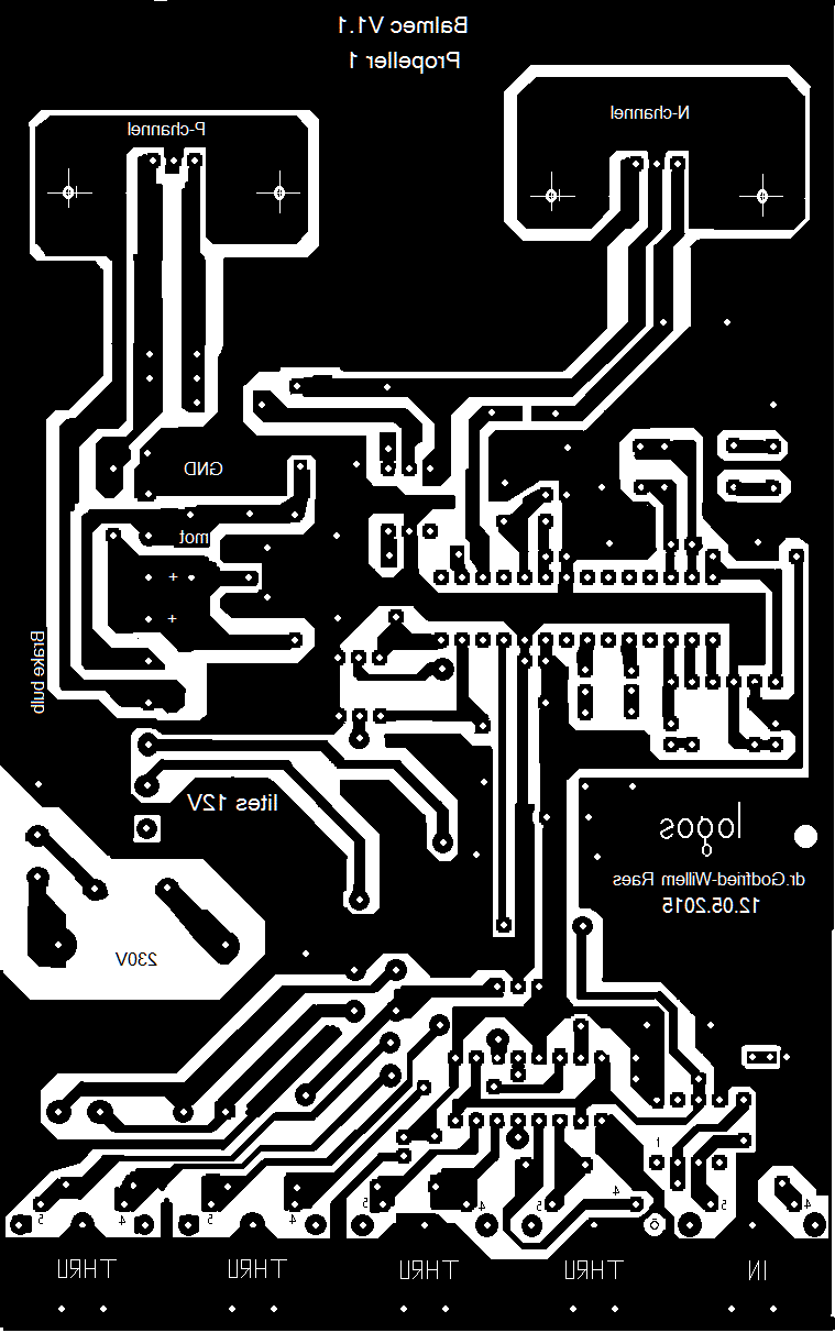
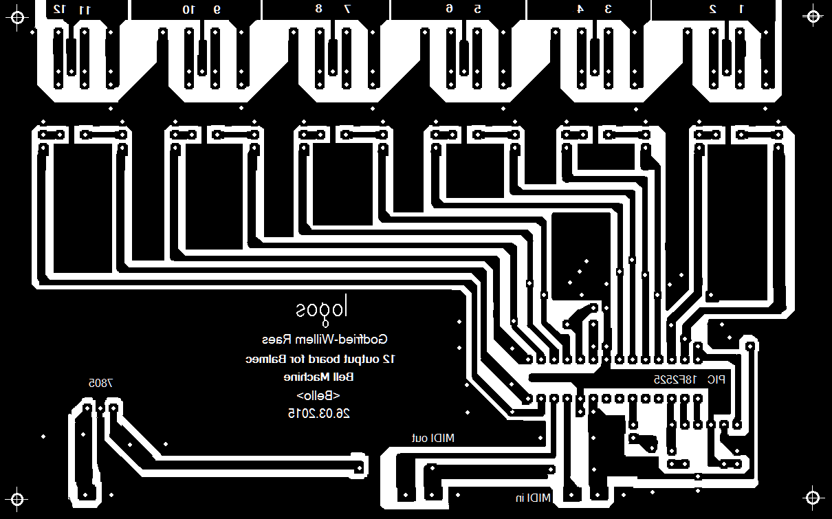
- 28.04.2015: Propeller 1 failure: it switches on, on powerup... Something goes very wrong here. When we took the board out, the microcontroller was performing o.k., however the IRL640 Mosfet appeared to be molten down. We have no idea as to the cause here. We removed the VDR soldered on the board across the motor load, as when this triggers on spikes it could effectively cause a short. We replaced it with a 220nF capacitor, to smooth out the PWM carrier somewhat. We noticed that the Mosfet can get very hot. We might have to mount it on a larger heatsink. Got everything working again, but we have bad feelings as we cannot clearly trace the cause of the failure. Thus we started drawing out a new design for the circuit as well as the PCB. The new circuit has support for braking, using a P-channel power mosfet. This implies quite some changes in the firmware of course. Here is the new circuit: And this is what the PCB looks like: Hopefully we have the time to etch and solder this before the Antheil piece goes into production... this weekend. In fact it would be a good idea to provide some place on the PCB for a simple SMPS 12V power supply, as this would allow us to mount two red LED spotlights on this propeller as well...
- 29.04.2015: Further testing of all Balmec components with the Antheil midi file. Two 50 meter long differential midi cables soldered, using DMX wire with characteristic impedance 110 Ohm. Signal quality tested using the oscilloscope. Further improvements on the PCB for prop1.
- 30.04.2015: Test run using the differential drivers and receivers with the 50m cable.
- 01.05.2015: First reality tests with the propellers mounted on stage in Zwevegem. The fuses did blow when trying to use them on very high speeds... Recalculating everything. Apparently the use of single sided rectification in the motor drive for propeller 2 and 3 causes the differential safety switches to blow.
- 02.05.2015: Circuit improved by adding isolation transformers in the motor supply as well as double sided rectification. We will not have the time to implement it immediately and before tomorrow's performances, as we have to order the required 1kVA transformers. Here is the improved circuit for propeller 2. And here for propeller 3. The IGBT on propeller 3 did go to heaven. We repaired it.
- 03.05.2015: First three performances of Ballet Mecanique with the three propellers and the <Bello> robot. In the meanwhile we redesigned the circuit and the PCB for propeller 3. It will after this upgrade, use a 1.6kW isolation transformer.
- 04.05.2015: PCB for propeller 3 design finished. Components ordered from Farnell.
- 06.05.2015: New version 3 board drawn, etched, drilled and soldered for propeller 3. Isolation transformer mounted underneath the propeller H-beam. Firmware simplified. No braking on slowdown now. This is the new board:
- 07.05.2015: Propeller 3 fully tested. It seems to work to perfection now.
- 08.05.2015: Experiments carried out with a resonator on propeller 3. Construction of a bell for note 66 on <Bello>. Herefore we use a tuned U-shaped steel beam (cut off from a rectangular 100 x 50 x 4 piece of construction steel). For the mechanism we use a modified solenoid taken from a Friedland modern doorbell. Coil resistance is only 3 Ohm. The mechanism appeared to be very poorly made of all loose parts just held together in a plastic enclosure. We impregnated it in epoxy rosin and provided in two solder lugs for the electrical connections. As the ON-current goes up to 4 A for this coil, we have to take measures in the firmware to reduce maximum velocity values. The coil windings do not look like capable to withstand this current, except on very low duty cycles. Here is the result: This bell is mounted on the backside of the robot.
- 09.05.2015: Construction of bells for the missing note 62 and 63, following the same recipe as done for 66. These bells also will have to find a place on the backside. Mechanisms constructed: modified 24V US-doorbell mechanisms modified to operate on 12 V by switching the coils in parallel.
- 10.05.2015: Two red LED spotlights added on Propeller 1. Just like with the other propellers, the flashing speed can be controlled with the velocity byte in the note on command.
- 11.05.2015: Etching and soldering of the new board for propeller 1
- 12.05.2015: Vigortronix VTX-214-010-112 power modules (12V) ordered from Farnell, as well as TO220 heatsinks. Prop1 board finished.
- 13.05.2015: Mounting of the 12V module and the new board on propeller 1.
- 14.05.2015: Testing of the new board. Problems: the P-channel mosfet seems to conduct all the time... Recalculation required.
- 15.05.2015: Bug found and cured. The 1M Ohms resistor on the base should go to pin 4 of the optocoupler (emitter) whereas we had it faulty to the collector.
- 01.06.2015: Construction of a better bell for note 68 for <Bello>. This uses a thick and expensive cast bronze dome bell we digged up from our stock. It is driven by a modified US doorbell mechanism, used with the two coils in parallel such that the nominal voltage becomes 6V. However we operate it on 24V as we need quite some force to bring the shell in full resonance. Of course duty cycle has to be kept low now. We left the original 68 bell (thin stainless steel shell) in place on the front side, disconnected ( grey wire). It can later be replaced with a small good quality bell to extend the trebble (note 94). The new 68 bell found a place on the backside of <Bello>. The sound is excellent now.
- 02.06.2015: Wiring bug discovered in <Bello>. We had bell 68 connected to P1.2 (serving note 88) where it ought to go to P1.6. The ordered stainless steel shells came in from Demar Lux. Size 106 x 3, AISI304 sounds 91.4, size 154 x 2 AISI304 sounds a slightly too low 74, so we can use it as a bell for note 73, as yet double used with the bell for note 51 (the Siemens bell). Size 204 x 2, AISI304 sounds a slightly high 64. A suitable bell for 69 as yet not found. In implementing note 73 on the second pulse board P2.4, we discovered a soldering mistake: a short from the output to ground, causing the bell magnet to remain activated. After repairing, this worked fine again. New firmware uploaded in the PIC controller for pulse board 2. Firmware coding for board 1 adapted but not yet uploaded.
- 03.06.2015: Further firmware debugging, as we discovered some shakyness in its performance. Code for pulse board 3 changed: the bottom light is now mapped on note 119. Test code in GMT changed accordingly.
- 05-14.06.2015: Firmware debug. Compiler upgrades. Nothing but problems... Documentation in headers for firmware versions for pulse board 2.
- 15.06.2015: Finally problem solved. New firmware for pulse board2 works. There was a bug in the newest version of the Proton+ compiler: handling of dwords (32-bit variables) became a complete mess.
- 17.06.2015: Firmware for pulse board 1 revised as well.
- 26.06.2015: All firmwares in pulse boards 1, 2 and 3 replaced with the new coding. Only the hub board remains to be upgraded now.
- 27.06.2015: Hub board upgraded. After testing it came out that all velocity lookup tables needed a multiply by 2.4 to compensate for the much higher loopspeed now. Thus we had to revise the firmware in all four chips again. Now we are at version 2.1 for all boards. First tests appearing to be o.k. now. All firmware now has controller 30 implemented.
- 16.07.2015: All three propellers and the <bello> robot used in the fifth full-evening Namuda production: 'Impossible'. The propellers are installed in the lodge, the <Bello> robot in the tetrahedron. Fuse on propeller 3 blown. We had 6.3A instead of the calculated 8A.
- 23.07.2015: The three propellers and the Bello robot worked flawless in our namuda production 'Impossible'.
- 07.09.2017: <Bello> used in the orchestration of 'Parade' by Erik Satie.
- 23.01.2019: <Balsi> finished and presented at the robotorchestra concert in the Logos Tetrahedron.
- 03.09.2019: Propeller 1 and Propeller 3 with Lara Van Wynsberghe on the road to Tongeren Basiliek) for an orchestral performance of Ballet Mechanique for B-Classic. No problems reported.
- 10.02.2022: Propeller 1 set up and found defective... The IRL640 MOSFET found to be burned out and fully shorted. We replaced it with an IGBT, type IRGB14C40L. After a while, it also gave up... All three propellers set up in the lodge for a rehearsal with Ictus. We revised the firmware for propeller1 and implemented a minimum speed for the propeller. The IRGB14C40L IGBT was replaced with the last component of this type we had in stock. Apparently, this type is by now obsolete.
- 02.03.2022: After testing with the IRGB14C40, we found it fused again... Test replacement with a IKP28N65 IGBT, rated for 650V and 38A. Power 130 W. Braking connector loosened, however, not certain at all that this part of the circuit is the cullprit. Should we lower the PWM base frequency? Where are the two 50 meter long differential midi cables soldered, using DMX wire with characteristic impedance 110 Ohm that we made for this project in 2015???
- 11.03.2022: Propeller 1 failure... cause? New/bad DMX wiring? Shaky MIDI? Terrible control software? (PD or Max/msp?)...
- 14.03.2022: IRL640 on Propeller 1 board replaced. PWM frequency lowered to the lowest possibl;e value now.
References:- Elsto, DC-motor catalogue
- George Antheil, 'Bad Boy of Music', Da capo press, New York, 1981 (ISBN: 0-306-76084-3)
- George Antheil 'Ballet Mechanique', full score
- Gillon, E. "Elektrotechniek", deel II: Elektrische Machines, ed.Standaard Uitgeverij, Antwerpen 1969.
- Edward Hughes, 'Electrical Technology', ed. Longmans, London 1960.
- Funke + Huster Fernsig Gmbh. (http://www.fhf.de)
- Humphreys, Julian (ed.), Philips Power Semiconductor Applications, ed. Philips Export, Eindhoven 1991
- Infineon, IGBT datasheet.
- Infineon, IKP28N65 datasheet.
- Paul Lehrman 'Introduction to Ballet Mecanique' (PDF)
- Raes, Godfried-Willem 'Bellenorgel' (1972)
- Raes, Godfried-Willem 'Expression control in musical automatons' (-2022)
- Werkhuizen Lentz bvba: www.werkhuizenlentz.be (CNC lathe and milling works)
Order numbers spare parts and special (harder to find...) components:
- Bridge rectifier 40A - 1kV: 9380841 (Farnell) type CM40010
- 1mF/250V Electrolytic cap, snap in, PCB, Epcos B43501-C2108-M: Farnell 1839316
- 5-pole DIN socket, PCB, Preh metal 71251-050: Farnell ord: 1193184 (used as MIDI input connector)
- 5-pole DIN socket, PCB, Plastic Hirshmann MAB5 SH, Farnell ord.: 1944987 (used as MIDI balanced line driver output connectors)
- Halogen bulb 205W, Osram (Conrad) (Used as brake resistor on Prop 2 and 3)
- Kingbright LED cluster lights. (2 on each propeller, 2 on Bello)
- Vigortronicx VTX-214-010-112 (12V/0.83A SMPS module), Farnell ord.:240-1054
Last update:2022-03-14