|
Microtonal Musical Robot Research project on the development of new tools for musical expression at the University College Ghent
|
|
<Fa> a robotic bassoon dr.Godfried-Willem RAES 2009 - 2016 |
|
Microtonal Musical Robot Research project on the development of new tools for musical expression at the University College Ghent
|
|
<Fa> a robotic bassoon dr.Godfried-Willem RAES 2009 - 2016 |
Robot: <Fa>
This musical robot belongs to the category of our automated classical music
instruments: the bassoon. The reason for taking up a bassoon automation project
has to do with the simple fact that bassoon players of quality are getting extremely
rare. In fact, it should be considered an endangered if not already almost extinct
species... Furthermore, we do like the bassoon sound and thought it would be
a most welcomed timbral component in the robot orchestra. The brass section
is well represented and covers the bass side pretty well, but as far as woodwinds
go, there was a noticable gap. The approach here was an attempt to realistically
automate an existing and basically unmodified instrument, and thus it does use
a classical bassoon. We started the design of this robot after the quite successfull
realisation of our oboe playing robot <Ob>. Hence the sound mechanism
is based again on an acoustic impedance convertor with a capilary, driven by
a motor compressor. The original crook of the bassoon fits very precisely into
this part made on the lathe from massive brass. As
mandatory in such an impedance convertor, we first have an anticonical part
driven by the motor compressor leading into a capilary traject, after which
follows a conical part adapted to the instrument to be driven, in this case
the crook of instrument at the end where normally the double reed is mounted.
The longer the (linear) length of the capilary and the smaller its diameter,
the more the sound is determined by the acoustic properties of the instrument
alone, but obviously at the same time, sound pressure goes down. Thus we always
have to find a compromise. In this case we did choose the diameter of the capilary
at 3 mm and the length at 6 mm. As yet we have no mathematical model for this.
If a physicist could help us out here with some math it would be highly welcomed.
Sofar we sufficed by turning different shapes on the lathe and, by successive
approximation, getting to an optimum result. Very time consuming, indeed.
Here are some pictures of the bassoon we used, -a french Artla instrument-, before any treatments took place, in the left pictures and after placement of the valves in the right picture.:
front
side
back
with
valves...
From an acoustical point of view, the bassoon is a pretty poorly designed instrument. It has a narrow conical bore with no less then 27 holes. A pretty complicated valve and lever mechanism renders it possible for a human player to open and close all these holes with just ten fingers. The resonance characteristics show up a pretty low Q-factor for the fundamental note played and therefore playing exactly in tune is pretty demanding for a human player and asks for a very good lip control. Despite the many valves and mechanics. At the other side of the medal though, this makes is possible, in a robotic design, to implement all kinds of tuning and intonation subtleties even without using complicated fingering combinations.
Any automation project for an instrument normally played by humans, should start off with a proper analysis of how it is traditionally played. Therefore we started off with a thorough study of the textbook fingering table for the bassoon:
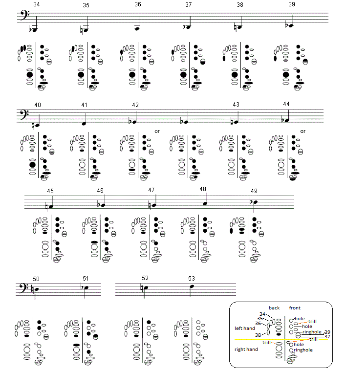
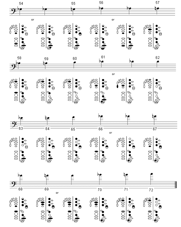
From this study, combined with questioning a professional bassoon player, we can learn which keys are acoustically fundamental and distinguish the ones only added for the playing comfort of the musician. Trill-valves (3) as well as octave speaking valves (whisper valves) may not be essential for a robot. Thus of the 27 valves found on the instrument, some can be considered optional. Also, it revealed of interest to study some literature on the history of the instrument, since that explains the growth of the mechanism into its present day state very well. Note that on the baroque bassoon for instance, like on the recorder and the traverso, many pitches were played using cross-fingerings. These are awkward for players in fast passages, but there is no objection against them on an automated instrument.
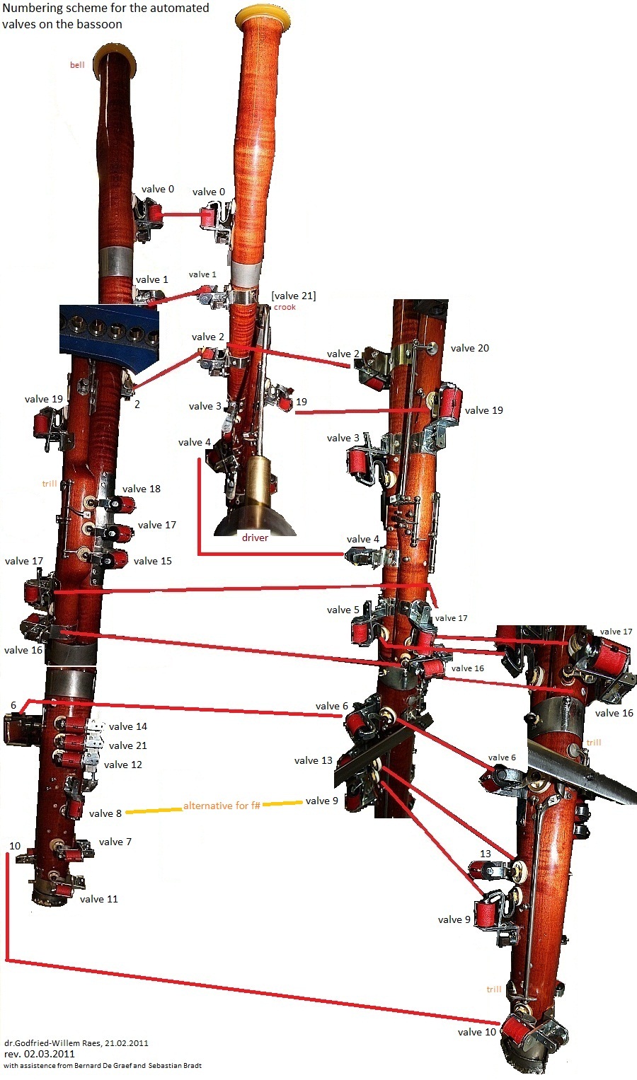
Although we first considered leaving all mechanics on the instrument intact and replacing the human fingers with action solenoids -this was what we did in our automated oboe- , some early experiments revealed clearly that this would lead to a lot of unwanted clicking noises. Therefore we decided to get rid of all the mechanics and replace them entirelly with flat pallet solenoid valves working directly on the tone holes. We took a risk here, as we mounted all the valves directly on the instrument, knowing that the mechanical load on the wood would be quite a bit higher than in the traditional instrument. To make sure we would not crack the bassoon and ruin the internal bore, we constructed well fitting saddles from 0.8 mm thick stainless steel plate, for each of the solenoid valves and fixed them lightly with very short plate screws into the wood whereby the real sticking force is realised by glueing the assemblies using a special silicone compound. This job alone took almost a month of work, in part also because the silicone compound takes about 24 hours to cure. The results of this procedure will be clear in the photo collage underneath:
Once we got the sound driver and all relevant valves automated, we had to design
the electronic circuitry as well as a mechanical chassis to hold it all together.
For the electronic side, we first (that is, the version operational until september
2012) used a similar design as for the oboe <Ob> and most of the brass
instruments. Although a volume control circuit was added to improve on earlier
designs, we were not completely satisfied with the result. In september 2012
, after the good experiences with the realisation of our <Klar> robot,
we designed a new compressor driver board taking advantage of the 32-bit capabilities
of the ARM processor.
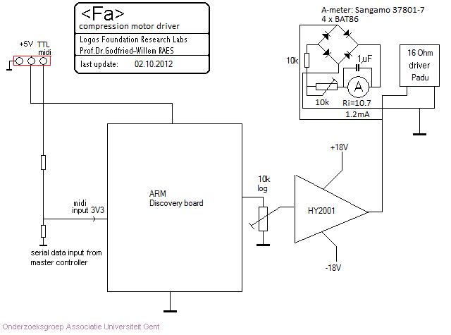
An important aspect of the firmware for the ARM processor used here, is that
we had to implement a formant around 500Hz in the driving source signal. This
conforming to the findings published by F.Fransson in 1966, where he proves
clearly that this formant cannot be attributed to the bassoon as a resonator
but solely to the action of the double reed. The formant filter implemented
affects the partials listed below. Note that notes higher than midi 60, do not
have this formant, note 71 being at the center of the formant frequency itself.
Calculation results for overtones falling within the formant range of the bassoon
Fundamental note , multiplier, frequency, fractional note
note= 34       partial: 9    frequency= 524.4343  note= 72.0391
note= 35       partial: 8    frequency= 493.8833  note= 71
note= 36       partial: 8    frequency= 523.2512  note= 72
note= 37       partial: 7    frequency= 485.0696  note= 70.68826
note= 38       partial: 7    frequency= 513.9134  note= 71.68826
note= 39       partial: 6    frequency= 466.6905  note= 70.01955
note= 40       partial: 6    frequency= 494.4413  note= 71.01955
note= 41       partial: 6    frequency= 523.8423  note= 72.01955
note= 42       partial: 5    frequency= 462.493  note= 69.86314
note= 43       partial: 5    frequency= 489.9943  note= 70.86314
note= 44       partial: 5    frequency= 519.1309  note= 71.86314
note= 45       partial: 5    frequency= 550.0001  note= 72.86314
note= 46       partial: 4    frequency= 466.1638  note= 70
note= 47       partial: 4    frequency= 493.8833  note= 71
note= 48       partial: 4    frequency= 523.2512  note= 72
note= 49       partial: 4    frequency= 554.3653  note= 73
note= 50       partial: 3    frequency= 440.4972  note= 69.01955
note= 51       partial: 3    frequency= 466.6905  note= 70.01955
note= 52       partial: 3    frequency= 494.4413  note= 71.01955
note= 53       partial: 3    frequency= 523.8423  note= 72.01955
note= 54       partial: 3    frequency= 554.9917  note= 73.01955
note= 55       partial: 3    frequency= 587.9932  note= 74.01955
note= 56       partial: 2    frequency= 415.3047  note= 68
note= 57       partial: 2    frequency= 440  note= 69
note= 58       partial: 2    frequency= 466.1638  note= 70
note= 59       partial: 2    frequency= 493.8833  note= 71
note= 60       partial: 2    frequency= 523.2512  note= 72
note= 61       partial: 2    frequency= 554.3653  note= 73
note= 62       partial: 2    frequency= 587.3296  note= 74
note= 63       partial: 2    frequency= 622.254  note= 75
note= 64       partial: 2    frequency= 659.2551  note= 76
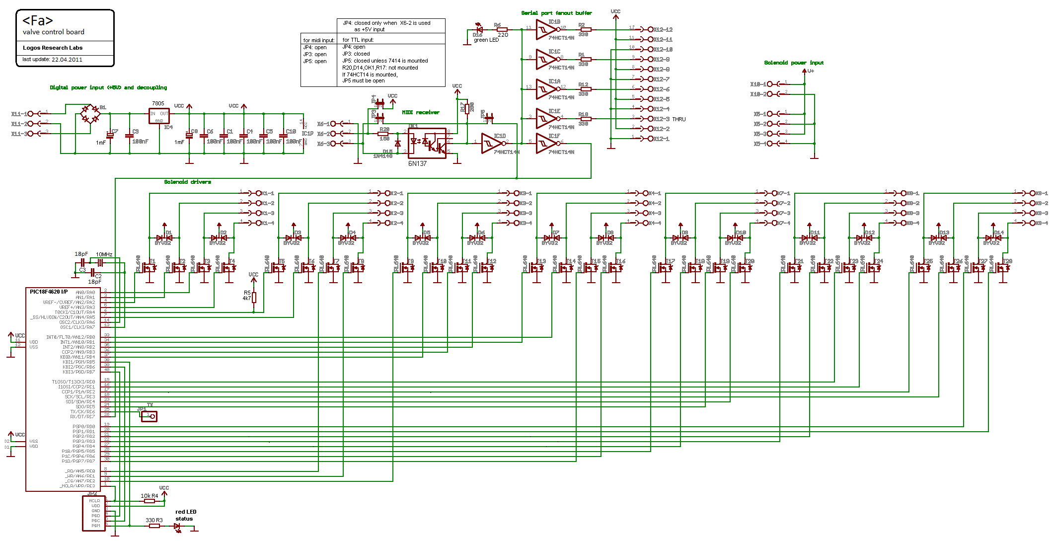
For the control of the valves and the fingering combinations, we used a Microchip 18F4620 microcontroller, for it can handle many output pins. The board designed has provisions for a maximum of 28 solenoid valves. Ample for this robot. The firmware for this controller, making extensive use of lookup tables, was developped with the Proton+ compiler in PicBasic combined with the MPLAB programming environment offered by MicroChip.
The thirth and last circuit board, houses a small Microchip 18F2525 processor and takes care of all visual aspects, including the motor implemented to give the robot some physical movement possibilities. An analog input is used to read the tilt sensor. This board serves at the same time as a midi-hub for the other boards.
Obviously, the different components also need power. Hence we designed all analog power supplies as needed. We carefully stayed away from switched mode power supplies, since in all too many earlier projects they were at the origin of many problems with reliability and audible artifacts.
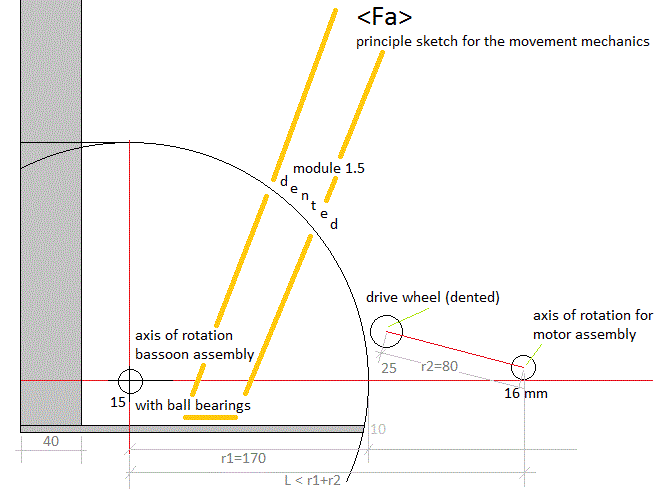
Since some movement of the bassoon is quite normal in human performance, we wanted to implement that as well. Hence we suspended the entire bassoon and motor drive assembly on a spindle such that it is allowed to rotate over an angle of about 30 degrees.
A novel aspect of the design of this robot is the implementation of a fingered vibrato, conforming to the tradition in vibrato playing up to the second half of the 19th century. (cfr. Baines, 1957). The standard midi channel-aftertouch command was used to implement this. The lookup tables for the vibrato-activated valves reside in the firmware and are not user programmable. The value parameter for the aftertouch command is used to steer vibrato speed. Note that fingered vibrato can be applied to any sounding note, included the lowest note. This seems counterintuitive, as on a normal bassoon, as soon as any valve is opened when note 34 (B-flat) is playing, another note will sound. In this case however, we keep the excitation on the low note and use the valve opening the note an octave higher for fingered vibrato. The lookup tables used for fingered vibrato are based on carefull experimentation with the playing instrument. We remain open for suggestions as to alternate fingerings.
The ambitus implemented for <Fa> is: 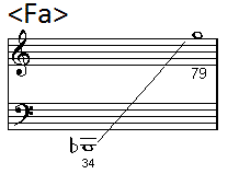
The circuit overview looks like: 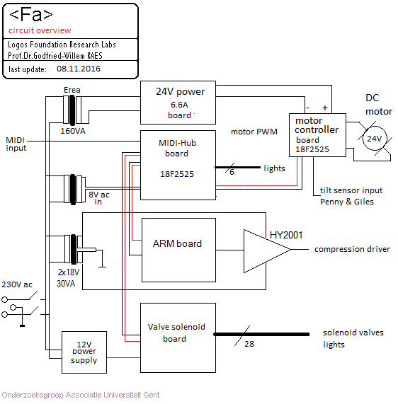 Details
can be found at the bottom of this page.
Only when integrated in the context of our Logos Robot Orchestra with its wealth of varied sensor systems allowing full interactivity, this automate becomes a true robot, with knowledge of the environment in which it operates. That's after all were its destination is to be sought.
Midi channel: fixed to 15 (counting 0-15).

Note Off: Implemented for all notes in the range. Starts a short decay (release)
on the playing note. The duration of the release is determined by the value
of the controller 19. For legato playing, note-off's can even be dropped, since
the instrument is monophonic.
Note On: Implemented for notes in the range (34-91) . Bassoon sound is only obtained using the normal range 34-79 however. Velo-byte is used for the level of the sustained sound portion. The lights are also mapped on notes, but make use of a range outside the normal range of the bassoon, i.e. the 0-5 range. For those lites the velo byte is implemented to make automatic flashing possible. The velocity value determines the speed of the flashing. With value = 127, the lites will be permanent on. With zero value, they will be off.
Controller 1 is used as a 'wind' controller and steers the noisyness of the generated sound, by mixing noise in the drive signal. With value 0, the signal is noisefree. A normal setting is 2.
Controller 2: LFO3 frequency applied to the filter. Default = 2. Advised setting:
2
Controller 3: Vibrato depth (LFO1 amplitude). Default = 20. Advised setting:
20, to turn vibrato off, set this controller to 0.
Controller 4: Vibrato speed. (LFO1 frequency). Default = 8. Advised setting:
8
Controller 5: Tremolo depth, amplitude modulation. (LFO2). Default = 0
Controller 6: Tremolo speed. (LFO2 frequency). Default = 0
Controller 7 is used as the general amplitude controller. This is the controller to use for all slow amplitude modulation related effects. It should be avoided to leave this controller on a high value (say above 80) for longer than required, since there is a risk of burning out the compression driver at long high sound levels.
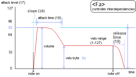
Controller 16 is used to control the slope of the attack. At value 127 the attack will be as steep (sudden) as possible. This controller will only have an effect if preceded with a note-off command, this to render pure legato playing possible. Decent sequencer software should offer you a possibility to set tracks for the <Fa> robot to monophonic synth, such that note-off's can be dropped from the sequence. A normal setting is value 80.
Controller 17 is used to control the maximum sound level during the attack period. The normal value can be taken as 127 (maximum).
Controller 18 is used to control the duration of the note attack. A normal setting is valkue 90. The interdependencies of these controllers together with the velo byte is shown in the graph below:
Controller 19: Release time. If legato playing is in use (meaning we do not send note-off's) the setting for this controller will be overridden. If you use sequencer software that does not allow you to not send note off's, legato playing can be obtained by setting this controller to low values. A normal setting is 72.
Controller 20: Tuning. The basic tuning of the instrument can be shifted a quartertone upwards or downwards. At setting 64 the tuning corresponds to A=440 Hz. (Precision better than 1 cent).
Controller 21: Restricted use: steers mimimum motorspeed (only used for code development and adjustment of the electromechanics), Default = 72
Controller 22: Inclination controller for the movement. Default = 0 (Fully reclined position) . Value 10 corresponds to a fully vertical position.
Controller 23: Restricted use: steers maximum motorspeed (only used for code development and adjustment of the electromechanics). Default = 120
Controller 25: This sets the central frequency for the formant filter. For a good bassoon sound, one should stick to value 75 here.
Controller 26: Sets the Q-factor (the amount of resonance) at the formant frequency set with controller 25. For a bassoon the value should be 100.
Controller 27: For experimental use only. Echo mix, can generate multiphonics. Set to 0
Controller 28: For experimental use only. Echo feedack, can generate multiphonics. Set to 0
Controller 29: LFO3 filter depth. Large values give a quite artificial wha-wha effect. Normal setting: 21
Controller 30: Valve release time out.(only used for code development)
Controller 31: Does the same thing as aftertouch: fingered vibrato. However, it does not require to be sent again and again in a sequencer. The parameter sets the vibrato speed. Default = 0
Controller 40: Sets the range for the pitchbend command. Normally and by default we stick to plus or minus a quartertone. When set to 0, pitch bending is disabled. When set to 1 we have the normal default setting: -50 cents to +50 cents.
Controller 41: Detune amount of the first odd harmonic (duodecime). Not to be used on the bassoon. Normal setting: 0
Controller 42: Intensity of the duodecome component. Not to be used on the bassoon. Normal setting 0.
Controller 43: Wait time for the vibrato to be applied after the note-on command is received. Normal setting: 20
Controller 44: Wait time for the tremolo to be applied after the note-on command is received. Normal setting: 10. This can be used for flatterzunge effects. Not in normal playing.
Controller 66: Robot on/off switch. Setting this to 0 resets all controllers to their default start-up values.
Controller 67: Switches automated movement in function of the music played on or off. The inclination of the robot is a function of average pitch. When no notes are played, the robot will return to the reclined position.
Controller 69: Switches the automation of the blue eye-lights on or off. By default this controller is set to on. Values <64 switch the controller off, >= 64 switches it on.
Controller 100: alternate fingerings for the lowest 7 tone holes. Bit 0 is the tone hole for Bb, on the upper part of the instrument, bits 1 to 5 control the valves for the holes in the bass part of the tube. Bit 6 controls the lowest tone hole on the lower part.
Controller 101: alternate fingerings for the next higher 7 tone holes, all situated on the lower part of the instrument (this part has 12 holes)
Controller 102: alternate fingerings for the next higher 7 tones holes, 4 on the lower part of the instrument (bits 0 to 3) and 3 on the high part. (the high part of the instrument has 8 holes)
Controller 103: alternate fingerings for the last 6 tone holes. 5 are on the high part (bits 0 to 4) and the last one (bit 5) controls the small octave hole on the bottom of the crook.
Controller 123: switches the sounding note off, releases all keys, dims all the lights.
Pitch bend: The <Fa> robot can be used in any tuning system. In the drawing below we give the coding example for a fragment of a quartertone scale:
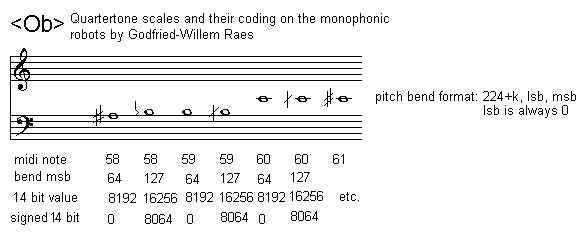 Most good sequencer
software (such as Cakewalk or Sonar) use the signed 14 bit format. Note that
one unit of the msb corresponds exactly to a 0.78 cent interval. To convert
fractional midi to the msb only pitchbend to apply follow following procedure:
if the fractional part is <= 0.5 then msb= 63 + (FRAC(note) * 128), if the
fractional part is larger than 0.5, we should switch on the note + 1 and lower
the pitch with msb= (1-FRAC(note)) * 128. Note off should
reset the pitch bend for the playing note!
Channel Aftertouch: used for implementing fingered vibrato. The parameter sets the vibrato speed. Note that vibrato cannot be applied to all notes! For note 34 for instance, all valves are closed and there is simply no valve to use for vibrato. Sending the command is harmless at any time. If it is impossible, nothing will happen. The parameter sets the speed wherewith the vibrato is executed. Note that most sequencers reset the channel aftertouch after every note off. To overcome that problem, we have implemented controller 31 as an alternative.
Program change: lets the user select alternate fingering lookup tables. (not yet implemented)
Lights: The lights are mapped on very low midi-notes as follows:
The velocity value determines the flashing speed. If value 127 is send, the lights will stay on without flashing. Value 0 switches the lights off. Whilst a light is switched on the flashing speed can be further controlled using the key-pressure command for the corresponding note.
Technical specifications:
Design and construction: dr.Godfried-Willem Raes
Collaborators on the construction of this robot:
Music composed for <Fa>:
Pictures taken during the construction in our workshop:
| Back to Main Logos page:index.html | To Godfried-Willem Raes personal home page... | To Instrument catalogue |  |
Robot: <Fa>
Na de bijzonder geslaagde realisatie van onze hobo spelende robot <Ob> besloten we nu ook het lage broertje van de hobo, de fagot, onder handen te nemen. Ook hier stond ons als doel voor ogen zo getrouw mogelijk de werking van de traditionele fagot te mimeren.
Mikrotonaal spel, inklusief kwarttonen zijn mogelijk door toepassing van non-standaard grepentabellen. Alternatieve grepen kunnen trouwens ook worden toegepast om klankkleurvariaties te bewerkstelligen. De hele opbouw van de elektromechanika voor het vingerwerk was uitermate tijdrovend, maar toch niet bijzonder moeilijk. Het vereist wel heel precies las-, tap-, boor-, zaag- en snijwerk. Bij de uitwerking opteerden we deze keer voor het geheel buiten werking stellen -en ook fysisch verwijderen- van alle kleppen en hefbomen nodig voor de menselijke bespeling. Het automatiseren daarvan zou immers onvermijdelijk tot vele overbodige bijgeluiden aanleiding hebben kunnen geven. Bovendien zijn de vingerkleppen op de fagot op sommige plaatsen (de duim bvb.) dermate dicht bij elkaar geplaatst dat het gewoon ondenkbaar was elektromagneten toe te passen met heel kleine afmetingen en toch voldoende kracht: die kunnen immers in het geheel niet worden gebouwd. Wanneer alle kleppen verwijderd worden, blijven we met een instrument voorzien van niet minder dan 27 toongaten. Elk gat werd voorzien van een eigen volkomen autonoom stuurbaar elektromagnetisch ventiel. In rust zijn nu alle toongaten dicht. De elektromagneten met de kleppen werden geheel op het lichaam van het instrument gemonteerd, een behoorlijk risikovolle onderneming. Immers het hout wordt nu belast met het gewicht van al die spoelen en er is dus een reeel risiko op barsten en perforaties. Om dit risiko zoveel mogelijk te beperken, monteerden we de spoelen op zadeltjes die op hun positie worden gehouden met uiterst korte inox plaatschroeven en voor de eigenlijke hechting werden vastgekleefd met een speciaal silikonen rubber (Loctite Bronze). Hierdoor wordt de kracht uitgeoefend door het gewicht van de elektromagneten over een relatief groot oppervlak gespreid.
Voor het klankmechanisme opteerden we voor een krachtige motor kompressor gekoppeld aan een akoestische impedantiekonvertor uitgerust met een kapilair van 4 mm, overeenkomstig de inwendige diameter van het bokaal aan de zijde van het riet. Deze konvertor werd uit een massief stuk messing met hoge precizie gedraaid op de draaibank.
De elektronische schakeling bestaat uit enkele afzonderlijk funktionele boards, de samenhang is zichtbaar in dit overzicht:

1. MIDI-hub board
Dit board en de 18F2525 processor staat in voor voor de lichten, gemapt op de noten 0 tot en met 5.
2. Motor control board:
18F2525 PIC processor. Staat in voor de besturing van de motor die het instrument doet bewegen. De firmware is struktureel gelijkaardig aan de firmware eerder ontwikkeld voor de <Ob> robot. De midi output laat toe de aktuele positie van de fagot in te lezen.
3. Kleppenbesturingsboard
De PIC op dit board, een 18F4620, staat in voor het juist toepassen van de vingerzettingstabel op de gevraagde te spelen tonen. Het PC board is in wezen hetzelfde als wat we ontwikkelden voor heel wat slagwerk robots zoals <Dripper>, <Casta>, <Troms>, <Psch>, <Xy> e.a. De achtentwintig beschikbare mosfet driver uitgangen volstaan voor het aktioneren van alle nodige kleppen. De firmware is uiteraard totaal verschillend. De Midi input (in TTL formaat) wordt toegevoerd vanuit het midi-hub board. De 5V voeding is autonoom on board uitgevoerd zodat we gevrijwaard blijven van power glitches. Details van het schakelschema zijn te vinden onderaan deze web-pagina.
Een bij deze robot ingevoerde vernieuwing is de volledige implementatie van vinger-vibrato, toepasbaar op elke gespeelde noot. Dit gaat terug op een historische uitvoeringspraktijk waarbij vibrato niet met de lippen werd verkregen, maar wel door een veelal lager gelegen toongat periodiek te openen of te sluiten. De opzoekingstabel voor de vingerzettingen werd samengesteld op grond van metingen en experimenten en ligt vervat in de firmware voor deze microprocessor.
4. Rietbesturingboard (Versie 1.1, nu versie 1.2):
Versie 1.1:
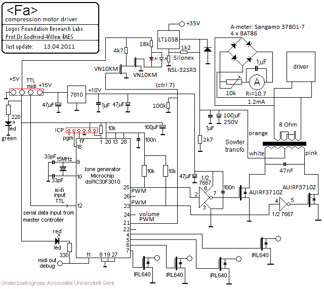
Hiervoor konden we hetzelfde printontwerp gebruiken dat we eerder
ontwikkelden voor <Aeio> en dat gesteund was op prototypes ontwikkeld
en gebouwd voor robots zoals <Korn>, <Hurdy>, <Autosax>, <Ob>
en <Bono>. Ook hier werd eenzelfde PIC mikrokontroller toegepast: de Microchip
dsPIC30F3010. De transformator was gebouwd naar een volledig eigen ontwerp door
het bedrijf Sowter in Engeland. De toepassing van een transformator hier was
ingegeven door de zekerheid dat we nu elke DC offset kwijt waren en bovendien
door toepassing van geschikte kondensatoren, konden zoeken naar de meest optimale
formant. De dsPIC firmware voorzag ook in de mogelijkheid ruis toe te voegen
aan het stuursignaal (via midi controller 1) waardoor het bijgeluid van speeksel
en lucht in het riet kan worden gemimeerd. Het dynamisch bereik bleek evenwel
onbevredigend en het was moeilijk een automatisch vibrato en tremolo's op het
dsPIC platform te implementeren. Daarom wijzigden we het gehele opzet van de
kompressor driver in 2012 alsvolgt:
Versie 1.2:

In deze versie maakten we gebruik van een 32-bit processor op een ARM discovery board. Dit bood heel wat meer mogelijkheden voor controllers en filters in de firmware. Ook de dynamiek kon heel wat groter worden dan wat met het dsPIC ontwerp kon worden bereikt. De Sowter transformator kwam te vervallen evenals de 36V voeding voor de driver. In plaats daarvan kwam een gewone 30 VA audiomodule van ILP (HY2001) waarmee rechtstreeks de driver wordt uitgestuurd.
Rekening houdend met het onderzoek van F.Fransson, gepubliceerd in 1966, hielden we er ook hier terdege rekening mee dat de karakteristieke formant in de fagot-toon rond 500Hz niet is toe te schrijven aan resonanties van het eigenlijke instrument, maar geheel en al voor rekening komt van de werking van het dubbel riet. Die formant werd dan ook in het excitatiesignaal toegevoegd.
Pas wanneer deze automaat wordt geaktiveerd in de kontekst van het Logos Robotorkest, waarbinnen hij vanuit een veelheid aan diverse sensoren en via doelspecifieke software kan worden aangestuurd, wordt hij een heuse robot. Daarin ligt ook zijn bestemming. <Fa> mag - na meer dan 15 jaar dagelijkse werking - worden beschouwd als een van onze meest suksesrijke realisaties inzake muzikale robots.
Construction & Research Diary:
 Stainless
steel ordered from Demar-Lux as required for the construction of the trolley.
Problem of the pivoting point for the movement studied.

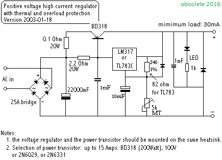
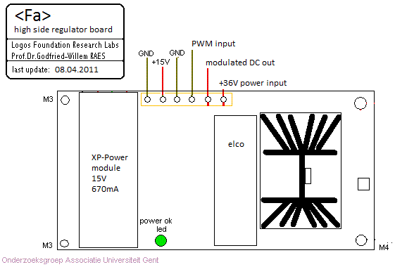 A linear regulator could also be an option. Initial test code for <Fa>
added in GMT. Midihub board component placement, soldering and wiring finished.
This board is now ready for programming. All mosfet's here are IRL640.
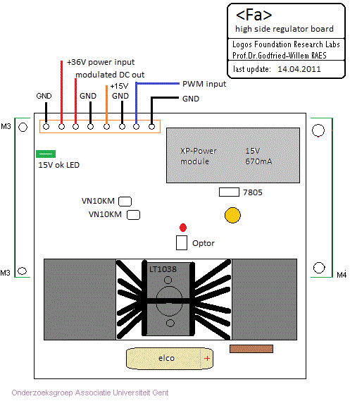 Construction
of a mounting plate in yellow massive polystyrene. Mounting of the backwheels
on the chassis, using M10 bolts and nuts.
 For the compression horn driver we use a 63W toroidal with 2x22V secondary.
This will give us 31V unstabilised measured over the 10mF smoothing capacitor.
Stabilisation is probably not required here. We will have to find out. Placement
of components checked with mechanical requirements with regard to freedom
of movement with the bassoon mounted in its cradle.
 New
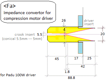
capilary impedance converter turned on the lathe to fit a Padu 100W driver.
(inner diameter 20mm). When we try it out, the power supply goes in overflow
and gets very hot. The high side driver goes into thermal protection and switches
off. Since things work -after cooling down- when we use only a single mosfet
at a time over half of the transformer primary winding, we conclude that the
driver is not properly working in push pull: the signals cannot be 180 degrees
shifted in phase as they should. Hence, the bug must be in the dsPIC code.
 Sowter transformer removed from the chassis.
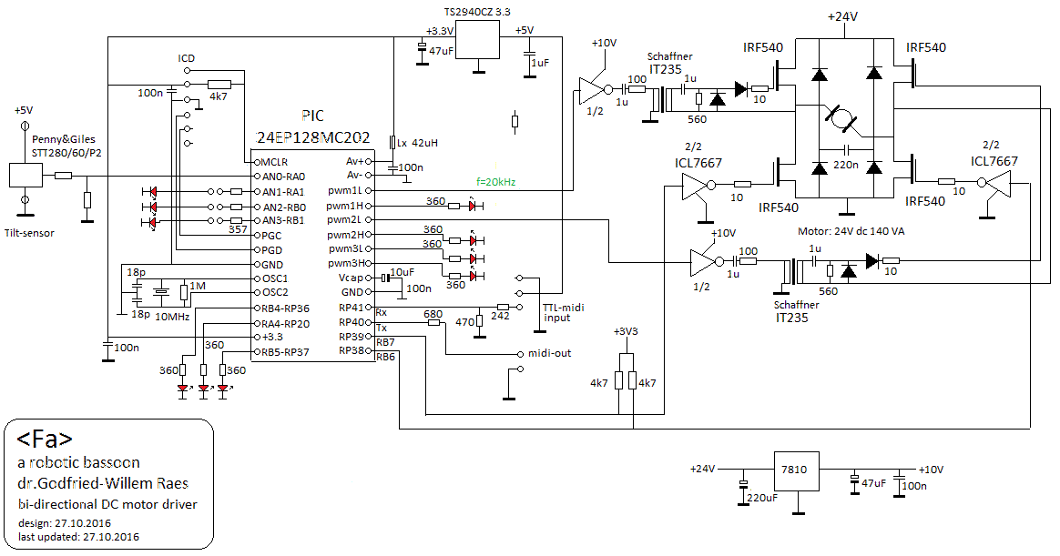 This
circuit easily fits on a eurocard PCB.
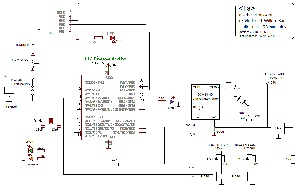 Here
we could use a United Automation Ltd. DCM24-40 motor/heat controller. This
module should be capable of delivering up to 40 A. The PWM frequency is rather
low (ca. 370Hz) and could lead to audible artefacts. Here is the data
sheet.
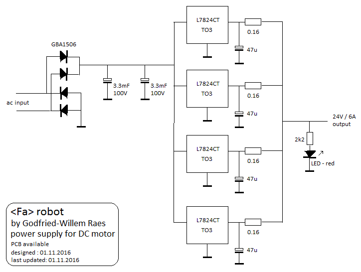 And, this is the PCB:
 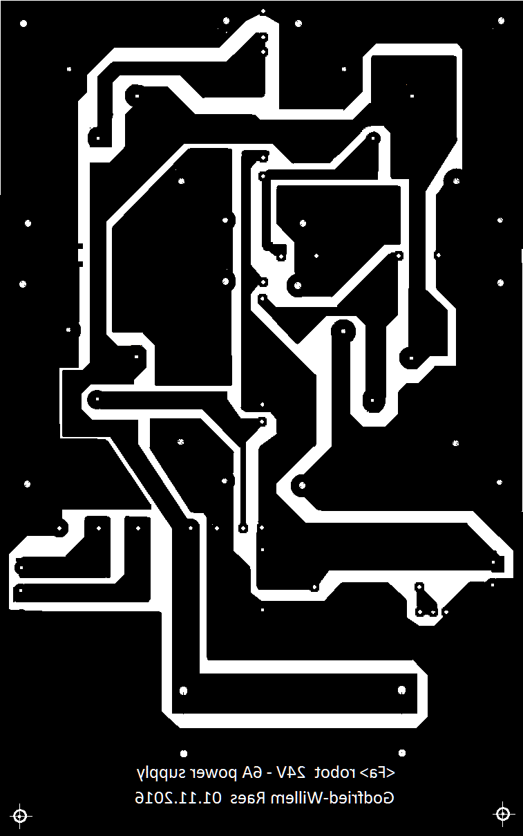 It
uses now largely obsolete voltage regulators in a TO3 packages, as we still
did have quite a few in stock. Each L7824CT can handle 1.5 A, so we get 6
A by parallelling them. The circuit fits nicely on a single Eurocard board.
We keep the original Erea transformer. Here is the assembled board:
 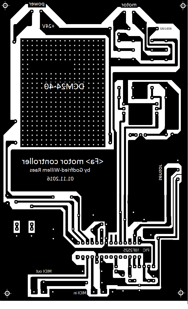 Soldering of this board will be done tomorrow... Both boards will be soldered
leadfree, for a change...
Soldering of this board will be done tomorrow... Both boards will be soldered
leadfree, for a change...To do:
Last update: 2025-12-14 by Godfried-Willem Raes
The following information is not intended for the general public nor for composers wanting to make use of our <Fa> robot in their compositions or orchestrations for the robot orchestra, but is essential for maintenance and servicing of the robot by our collaborators. It also might be usefull for people that want to undertake similar projects. Feedback is mostly welcomed.
Technical drawings, specs and data sheets:
Power supplies:
Wiring & circuit details midihub board:
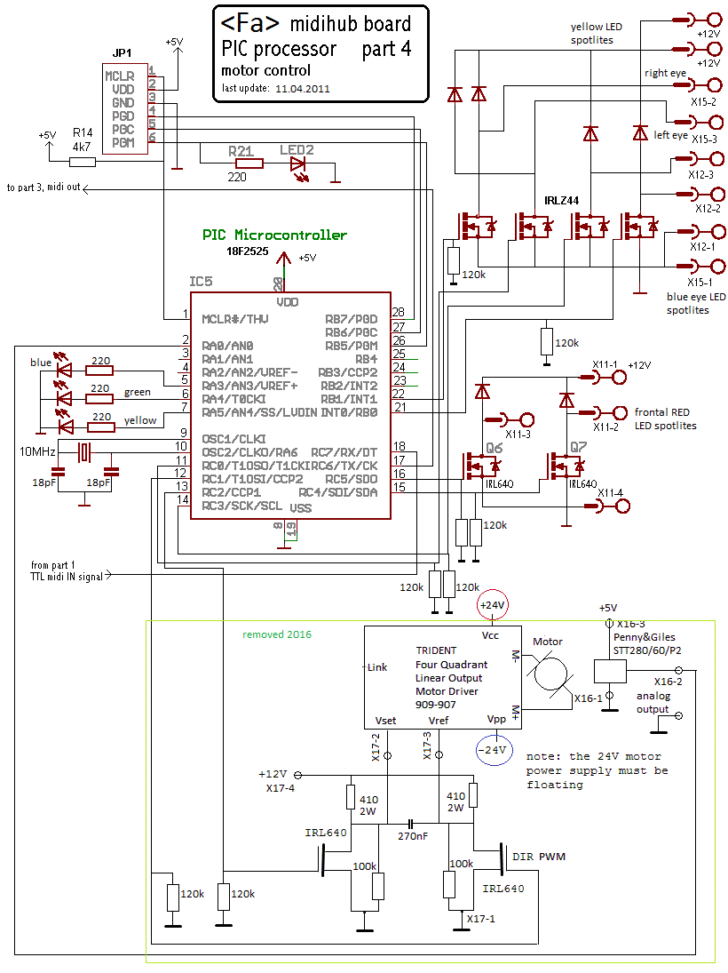
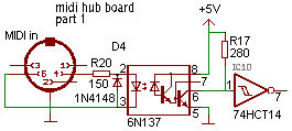
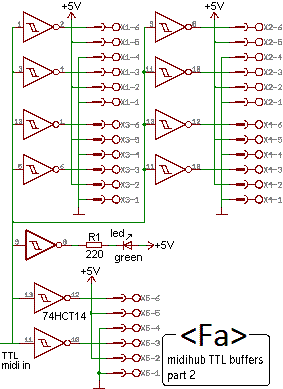
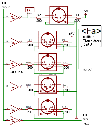
Circuit details solenoid driver board: (circuit drawing can be enlarged)
Mechanical construction drawings and welding plan:

Compression-driver:
Mounted now: Padu horn driver 100W / 16 Ohm.
Other types to investigate or to consider:
brand type nr power impedance normal use frequency range details dc resistance evaluation Atlas Sound PD60A 60W 16 Ohm PA type 100- 3700 Hz 60W @ 300Hz
2" voice coil
made in Texas (USA)
9.25 Ohm 10W @ 50Hz
used for <So>, V3.
Dayton Audio D1075T 75W 16 Ohm or
100V
PA type 180 - 6000 Hz 1.57 Ohm JBL JBL2426J 70W @ 800Hz
100W @ 1200Hz
16 Ohm Tweeter 500Hz- 20kHz 4W @ 50Hz Selenium D250-X1 150W @ 500Hz 8 Ohm 400 - 9000 Hz made in Brasil
Volume displacement: 0.5 l
6.1 Ohm 15W @ 60Hz
used for<Hunt>, V1.0
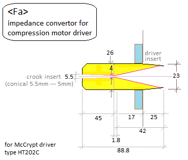
Mc CRYPT HT202C 25W rms 8 Ohm Tweeter titanium diaphragm
Kapton Bobbin and flat copper-clad aluminium wire voice coil. 41 Oz Strontium Magnet. [Conrad order nr. 452-055-06 & 2-986-954]
Sold as 100W power!
made in USA
rejected
This type burned out during the very first tests on <Fa>
PADU PD100 100W 16 Ohm PA type 100Hz - 10kHz made in China 11.72 Ohm in use now on <Fa>
also used in : Heli, Bono, Autosax, Klar, Horny, Asa
Realistic power horn
40-1236C
8W 8 Ohm PA type compression driver dismantled from horn
made in Taiwan
rejected
tried in Korn
burned out
Realistic TH15 15W 8 Ohm PA type compression driver dismantled from horn used in <Korn> RCA TW15W 15W 8 Ohm Tweeter 800Hz-20kHz made in Italy used in <Ob>
DC Motor:
Currie Technologies Inc., model XYD-15B, 24V DC, rated speed 3000 rpm, rated current 10A, output power 135Watt. At no load and operated on 24V, the motor draws 0.5 A. We bought one from All Electronics, cat# DCM-1506, ref. 1353583. It's a type of motor used for electric bicycles and small scooters. A more silent motor would be a better choice here. Datasheet.
Motor Controller: Trident Engineering. (A Maxon 4-Q controller is also possible, but much more expensive) [removed november 2016, as its power handling capacity was too low]
Motor Controller 2016: DCM24-40, made by United Automation Ltd.

Penny & Giles tilt sensor: Datasheet
Firmware for the motor controller: (Proton -now Positron- Compiler to be used)
Bassoon details:
Builder: Artla , foreign imported by Boosey & Hawkes, London. Made in France. The instrument must have been made after 1981, since in that year Buffet-Crampon came in the hands of Boosey & Hawkes. The serial number of the instrument is 356. The instrument was in perfect shape before we started its automation.
Download high resolution pictures of this robot:
References:
Baines, Anthony, 'Woodwind instruments and their history', ed. Faber and Faber Ltd., London, 1977 (1957). ISBN 0 571 08603 9
Bartolozzi, Bruno, 'New Sounds for Woodwind' , Oxford University Press, London 1982 (1967), ISBN 019 318611-x
Benade, Arthur H., "Fundamentals of musical acoustics",
Dover Publications Inc., New York 1990 (1976). ISBN 0-486-26484-x
Fransson, F. "The source spectrum of double-reed wood-wind instruments" In: STL-QPSR, vol7,nr.4, 1966, p.035-037 Weblink: http://www.speech.kth.se/qpsr
Raes, Godfried-Willem, "Expression control in musical automates", 1977/2023,
Raes, Godfried-Willem, "Logos @ 50, het kloppend hart van de avant-garde muziek in Vlaanderen", ed. Stichting Kunstboek, Oostkamp 2018.
Springer, George H., "Maintenance and Repait of Wind and Percussion instruments", Boston, 1976, ISBN 0-205-05012-3
Smith, Bob H., "An Investigation of the Air Chamber of Horn Type Loudspeakers", in: The Journal of the Acoustical Society of America 25, 305-312 (1953); https://doi.org/10.1121/1.1907038
Waterhouse, William, "Bassoon", entry in: The new Grove Dictionary of Musical Instruments, ed. Stanley Sadie, MacMillan Press Ltd., London, 1984. ISBN 0-333-37878-4
Weijers, Rembert, "Rieten ontwerpen en maken", Muziekuitgeverij van Teeseling, Nijmegen, 1978
http://bassoonoperator.blogspot.com/2011/01/formants-in-bassoon-spectrum.html