|
Microtonal Musical Robot Research project on the development of new tools for musical expression at the University College Ghent |
|
<Horny>
an automated french horn Godfried-Willem RAES 2013 |
|
Microtonal Musical Robot Research project on the development of new tools for musical expression at the University College Ghent |
|
<Horny>
an automated french horn Godfried-Willem RAES 2013 |
Robot: <Horny>
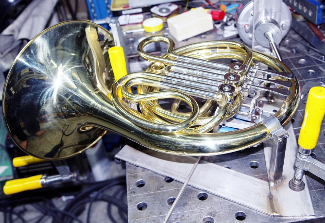
The design and construction of this automated instrument started with the purchase
of a brand new F-horn, made by Arnolds & Sons, model nr. AHR-301, serial
number 121267. It came with an extra short piece of tubing, such that it can
be turned into a Bb horn as well.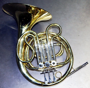
The horn has three rotary valves and force measurement revealed that the minimum
force required to start movement of the valves was 2 Newtons. The required movement
trajectory is 12 mm and the force required to fully push the valves raises to
2.5 Newtons. This determines the specification of the solenoid valves to be
used. The physical placement of the valves on the instrument however, dictates
a few more restrictions: the distances between the activation points of the
valves are 30mm and 20mm, so the use of standard Lucas Ledex tubular solenoids
(diameter 1" (25.4mm)) capable of meeting the specifications becomes problematic.
Hence we went for August Laukhuff register magnets with a pivoting action and
a force of 10 Newton.. The mounting width of these type is only 18mm. The solenoids
are connected in series with a 24V halogen bulb (10W), operating as a voltage
dependent resistor. As we power the solenoids from 48V, we now doubled the force developed at the
start of the trajectory. The starting force of these solenoids, even after carefull
adjustment of the anchor and the trajectory is only marginally large enough
otherwize. The solenoids are mechanically coupled to the valves using tractures
made of flexible M4 threaded nylon rod. Nuts and felt washers were used to minimalize
mechanical noise production. The operation of the valves is controlled by a
Microchip PIC controller type 18F2525. There are selectable lookup tables for
both the fingering on the F-horn and the Bb horn.
As we power the solenoids from 48V, we now doubled the force developed at the
start of the trajectory. The starting force of these solenoids, even after carefull
adjustment of the anchor and the trajectory is only marginally large enough
otherwize. The solenoids are mechanically coupled to the valves using tractures
made of flexible M4 threaded nylon rod. Nuts and felt washers were used to minimalize
mechanical noise production. The operation of the valves is controlled by a
Microchip PIC controller type 18F2525. There are selectable lookup tables for
both the fingering on the F-horn and the Bb horn.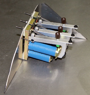
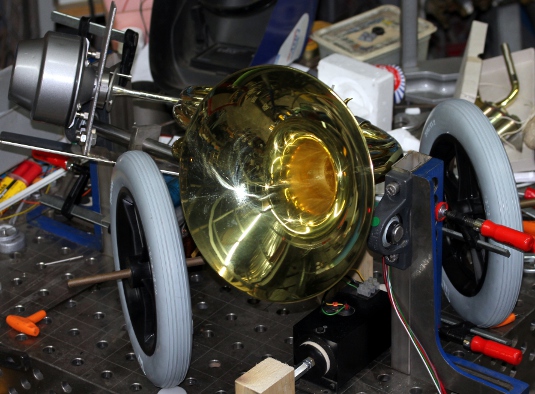
For the excitation of the horn we once again used a compression driver followed with an acoustic impedance convertor. In this case we used the original mouthpiece of the horn without any modification other than the construction of a new clamping system to connect the mouthpiece firmly with the driver. The compression driver is steered -after amplification- by an ARM-microprocessor.
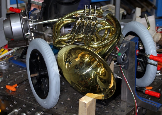
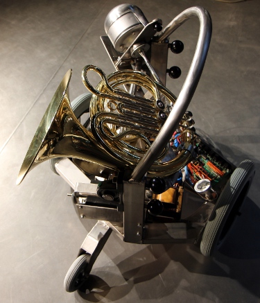
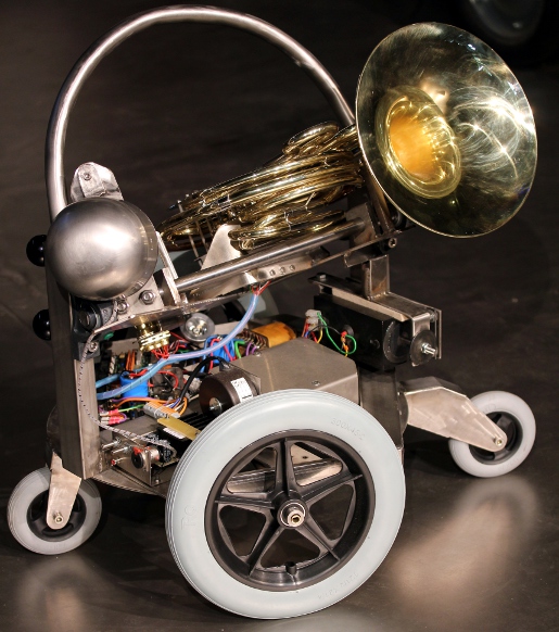
Horns are normally played with the bell pointing backwards. On occasions, composers do ask for the bell to be brought 'cor en haut', pointing to the audience. This request can for instance be found in the score of Strawinsky's 'Le Sacre du Printemps'. In our robot we also wanted to implement some form of control over the sound projection from the instrument. Since the mounting of the horn appeared to be quite complicated it was not possible to perform all calculations and drawings beforehand since for fluent motion it is mandatory to know the axis of equilibrium. Therefore we started by making the essential holding structure including the valve solenoids and the compression driver and only after that job was finished, we empirically found out where to place the balancing point. Unfortunately this balancing point appeared to come too close to the compression driver. Thus for technical reasons such as accessibility of mounting bolts and nuts and for ease of disassembly, we did move the axis of movement slightly to the backpoint. To restore equilibrium we sufficed by adding some extra weight. A stainless steel ladle at the same time serving as a protection cap for the compression driver fullfilled this function very well. As it came out, the final result is a bit crab like as the wheels had to be placed under a weird angle to the instrument.
Very probably this robotic horn is the very first horn player in music history that ever succeeded in playing his musical parts always perfectly in tune. Users and composers that like the 'out of tune-ness' of real hornplayers can always implement this as we gave the instrument ample possibilities to play in just about any imaginable tone system with high precision.
Power supply voltages and currents:
Midi Mapping and implementation:
Midi channel : 14 (counting 0-15).
Midi note range: (23-29), 35-94 if used as an F-horn with the appropriate crook
and controller setting. Note on, with velocity is implemented and has a wide
control range. The external input may be mapped onto the note range 110-119
(way above the normal ambitus and the extended range) This implements vocal/instrumental
multiphonic playing. Note that the range 30 to 34 is only available when the
Bb tube is inserted and the appropriate controller (#33) is send..
Note Off commands are required, but can be dropped for pure legato playing.
A note-off releases the valves and unpowers them. It starts the fast decay section
of the mouth driver according to the parameter set with controller #19. The
note release byte, if not 0, can be used for what it's standard function is
for. If used, it will override the setting of controller #19.
Controllers:
Controller 1: Wind controller, steers the amount of noise in the sound. Default
= x. Advised setting: 20
Controller 2: LFO3 frequency applied to the filter. Default = x. Advised setting:
2
Controller 3: Vibrato depth (LFO1 amplitude). Default = x. Advised setting:
20, to turn vibrato off, set this controller to 0.
Controller 4: Vibrato speed. (LFO1 frequency). Default = x. Advised setting:
5
Controller 5: Tremolo depth, amplitude modulation. (LFO2). Default = 0
Controller 6: Tremolo speed. (LFO2 frequency). Default = 0. Advised setting:
16
Controller 7: Global volume control. Can be used for crescendo and decrescendo
effects whilst notes are sounding. This also affects the sound color of the
instrument, as normal for horns. Default = 80
Controller 16: Note attack speed controller (0= slow attack, 127= fast attack)
. Default setting: 100. Advised setting: 25
Controller 17 is used to control the maximum sound level reached after the attack
time. This controller is always larger than or equal to the level set by the
velocity byte. For sfz or staccato playing, this controller must be set to high
levels and the velocity byte kept rather low. Default setting: 127. Advised
setting: 0
Controller 18 is used to control the speed of the transition between the attack
level once reached and the sustain or hold value set by the velocity byte.(0=
slow transition, 127= fast transition) default setting: x. Advised setting 50
Controller 19: is used to control the release time after reception of a note
off. Here again a value of 0 will give a slow release whereas a value of 127
will give a very fast release. Note that with very low values, the note may
not even turn off completely. Default setting: 96. Advised setting: 65. Note
that if real note-off commands are used, the release value sent with them, if
this value is not zero, will override controller 19, such that the value of
controller 19 will be set to 128-release value.
The following graph gives a picture of the mutual dependencies of all these controllers. Note that the implementation is different than what we have implemented in monophonic instruments build prior to <Fa>, <Asa> and <Klar>!
Controller 20: Basic tuning of the instrument. The range is + or - a semitone.(Defaults
to value 64 for A=440Hz)
Controller 21: minimum solenoid power PWM controller (for
development only) (default = 64)
Controller 22: Vertical inclination controller. (0-63= downwards, 64=central,
unpowered, 65-127= upwards). (default = 64)
Controller 25: Filter cut off frequency. Default = 62. Advised setting: 49
Controller 26: Filter resonance amount. Default = 90. Advised setting: 120
Controller 27: Echo mix. Default = 0. Advised setting: 2. Only use this for
experimental sounds, as it can generate multiphonics.
Controller 28: echo feedback. Default = 0. Only use this for experimental sounds,
as it can generate multiphonics.
Controller 29: LFO3, filter depth. Default = 20. Advised setting: 20. (large
values give a wha-wha effect)
Controller 30: Valve release time out after note-off's.
Controller 33: F-horn or Bb horn selector. (0= F-horn, 127 = Bb-Horn). On cold
boot the firmware will always assume F-horn. The setting of this controller
obviously changes the lookup table for the fingerings.
Controller 40: Bendrange for the pitchbend. 0= no bending, 1=+/- 50 cents. Default
= 1.
Controller 43: Wait time for vibrato start after
reception of a note-on command. Note that in legato playing, vibrato will continue.
The wait time starts again after a note off is received. Default = 100. Advised
setting 8.
Controller 44: Wait time for the tremolo (AM modulation) to start after a note-on
command. Default = 10. Advised setting: 3
Controller 66: Power on/off switch (0 = off, any other value is on). Power off,
resets all controllers to their cold-boot values.
Controller 100: Can be used to override the fingering used in the lookup tables.
Only the three lowest bits of the value are used. Bit 0 corresponds to the 1/2-tone
valve (the middle valve, named valve 1), Bit 1 to the 1-tone valve (the valve
closest to the mouthpiece, named valve 2), bit 2 to the 1 1/2-tone valve (named
valve 3). This controller can be sent any time, even when no note is sounded.
If you want a note to be played with a fingering different from the fingering
in the default lookup table, you have to send this controller right after the
note on command.
Controller 123: switches the sounding note off, unpowers the movement solenoid, dims all the lights. Does not reset any controllers.
Program change: not implemented so far. May be used later for interactive robotic modes of functioning, exploiting the audio input possibilities on the ARM-board.
Lights: The lights are mapped on very high midi-notes as follows:
With velocity values between 1 and 126, the lights will be flashing with speeds proportional to the velocity value. To switch them just on, use velo = 127. Velo=0 switches them off.
Pitch bend: implemented with a range of a semitone (a quartertone up or down). The coding for a fragment of a quartertone scale (here shown for the <Heli> robot, but its identical for <Horny>) is as follows:
 Most good sequencer
software (such as Cakewalk or Sonar) use the signed 14 bit format. Note that
one unit of the msb corresponds exactly to a 0.78 cent interval. To convert
fractional midi to the msb only pitchbend to apply, follow following procedure:
if the fractional part is <= 0.5 then msb= 63 + (FRAC(note) * 128), if the
fractional part is larger than 0.5, we should switch on the note + 1 and lower
the pitch with msb= (1-FRAC(note)) * 128.
Note that the pitch bend range on <Horny> can be modified with controller
40. By default this controller sets the range to plus or minus a quartertone.
By setting this controller to higher values, large continuous glissandi become
possible. Setting this controller to zero disables pitch bending.
Most good sequencer
software (such as Cakewalk or Sonar) use the signed 14 bit format. Note that
one unit of the msb corresponds exactly to a 0.78 cent interval. To convert
fractional midi to the msb only pitchbend to apply, follow following procedure:
if the fractional part is <= 0.5 then msb= 63 + (FRAC(note) * 128), if the
fractional part is larger than 0.5, we should switch on the note + 1 and lower
the pitch with msb= (1-FRAC(note)) * 128.
Note that the pitch bend range on <Horny> can be modified with controller
40. By default this controller sets the range to plus or minus a quartertone.
By setting this controller to higher values, large continuous glissandi become
possible. Setting this controller to zero disables pitch bending.
Classified by function, we have the following groups of controllers:
Technical specifications:
Design and construction: dr.Godfried-Willem Raes
Collaborators on the construction of this robot:
Music composed for <Horny>:
Pictures taken during the construction:
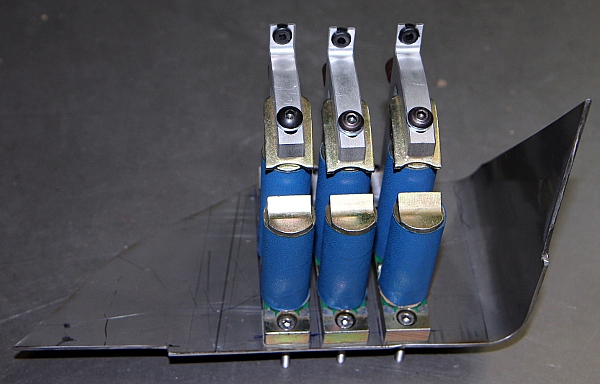
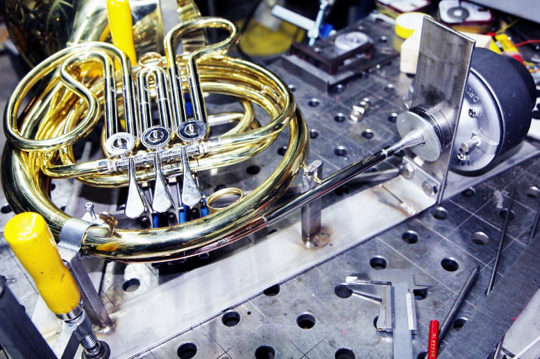 Valve solenoids:
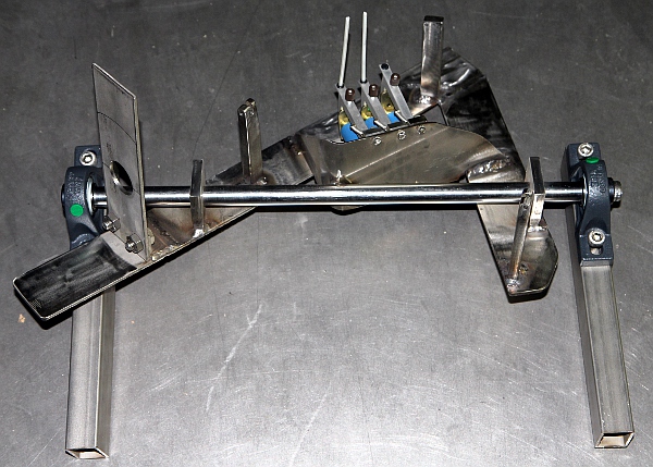
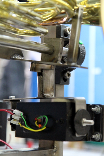
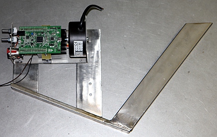
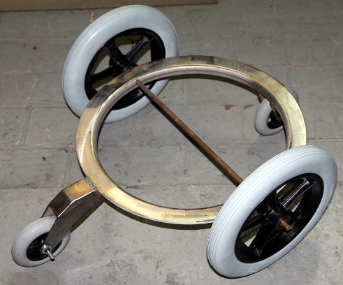
 Finished horn holding
part, with provisions for horizontal movement:
Finished horn holding
part, with provisions for horizontal movement: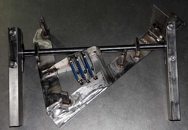
 and
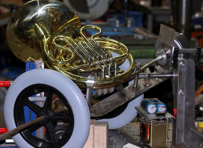
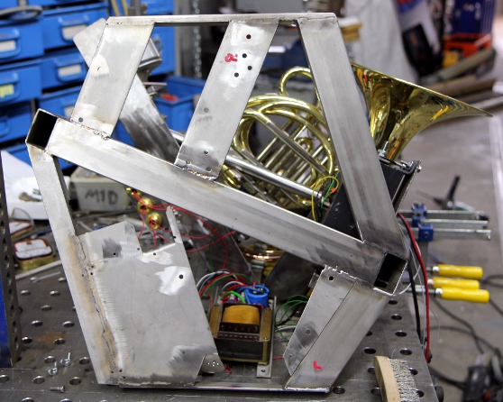
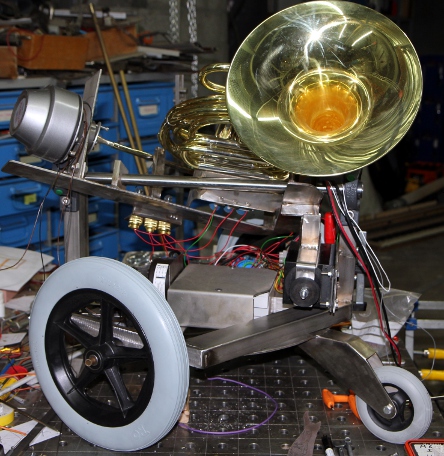
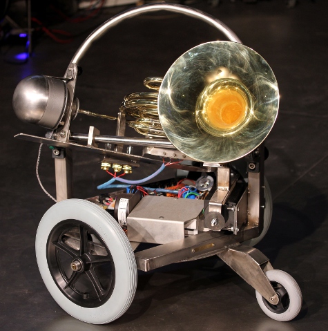
some views on the finished robot:
and
some views on the finished robot:
| Back to composers guide to the M&M robot orchestra. | Back to Main Logos page:index.html | To Godfried-Willem Raes personal homepage... | To Instrument catalogue |  |
Robot: <Horny>
Een nederlandse beschrijving is voorlopig nog niet beschikbaar.
Construction Diary:
Valve automation could also be done with Laukhuff pull down magnets (type
300800), having a traject of 10mm at a force of 10 Newton. (12V types have
R=13.5 Ohm and draw 900mA current). These are by design a lot more silent
in operation than the tubular solenoids. Another advantage is the fact that
they have a rotary motion, more or less corresponding to the rotary traject
the valves have to make. Thus unavoidable friction resulting from the use
of tubular solenoids with inherent linear motion can be avoided. On the negative
side however comes the fact that these Laukhuff solenoids are a bit sluggish.On
the picture we see clearly the mount for the compression driver and the mouthpiece
clamp. The driver can be taken away after loosening the two M10 bolts. These solenoids
consist of two coils connected in series, the shortest one has a DC resistance
of 25 Ohms and the larger coil, 32 Ohms. So when operated at their nominal
voltage of 24V, the shortest coil has 10.5V over it, the larger one 13.4V.
Design of the power supplies. Determination of a suitable horizontal balancing
point required to implement movement. Holes drilled in the valve-fingerplates
of the horn. Tractures made from M4 threaded nylon rod. Felt washers will
be required here.
If this simple solution is not workable, we will have to use the pulse-hold
boards and a dual voltage power supply. Halogen bulbs rated for 24V ordered
from Conrad and from Farnell. Their sockets (BA15s) still pose a problem as
they are very hard to find on the market. Furthermore they have one pole connected
to ground - a usual practice in cars and trucks-, making a complicated mechanical
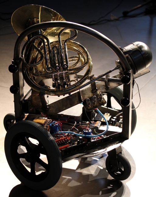
structure mandatory.With
the bell downward... And, with the bell upwards:
From the backside: 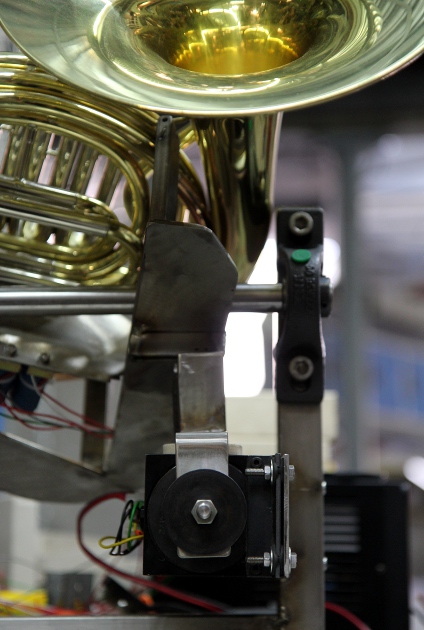 The bidirectional solenoid draws some 2.5A from the 24V power supply but seems
to work properly.
The bidirectional solenoid draws some 2.5A from the 24V power supply but seems
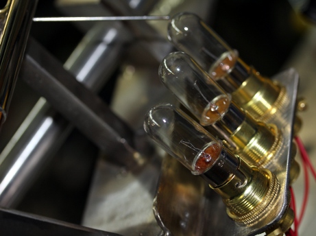
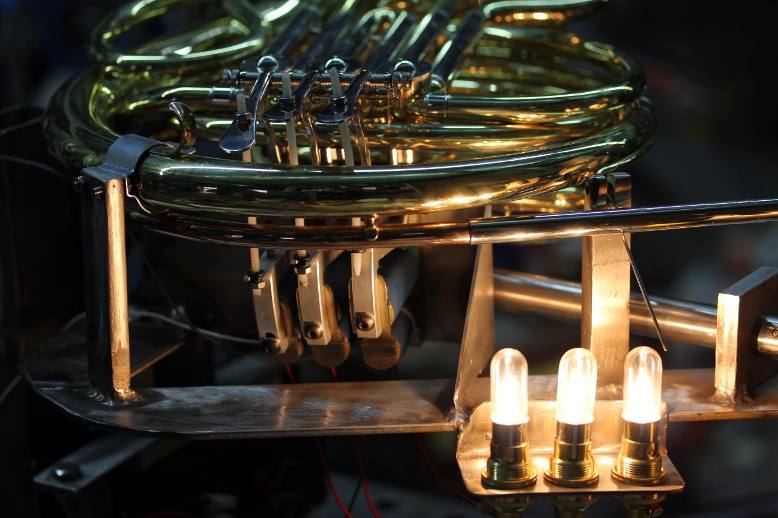
to work properly. Power
amp assembly nearly finished. Light assembly with BA15d lamp fittings finished
and welded in place. First tests with the power supply and the 10W/24V bulbs.
Power
amp assembly nearly finished. Light assembly with BA15d lamp fittings finished
and welded in place. First tests with the power supply and the 10W/24V bulbs. The
values for s ought to be close to unity (a bit larger in fact) and require
a 16 bit resolution over the range. Above this, enveloppe shaping and formant
filtering will have to be implemented.
The
values for s ought to be close to unity (a bit larger in fact) and require
a 16 bit resolution over the range. Above this, enveloppe shaping and formant
filtering will have to be implemented.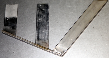
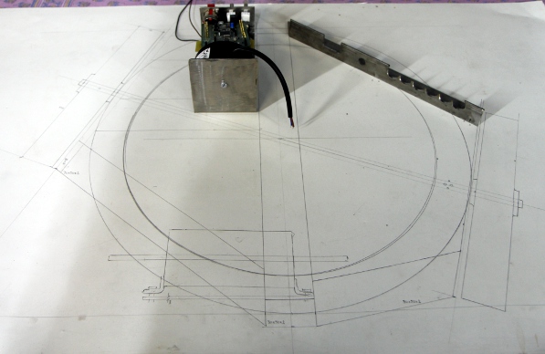
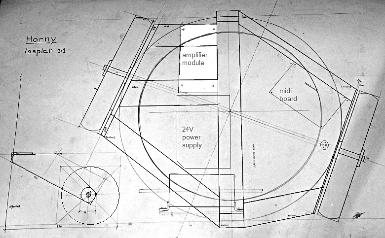 Test assembly
of the complete robot. Mounting and soldering of the stabilized 12V power
supply for the lights. Seems we have to redesign the positioning of the 24V
power supply as the positioning as drawn in 2D is practically impossible:
either the wheel axis or the rim underneeth are in the way. Eiher we have
to find another way of mounting, or else redesign the entire power supply.The
power supply is now bolted on the chassis with two M6 bolts and nuts. It can
be taken out easily. Start wiring of all power supplies. Electric test, DC
voltages checked o.k. Wiring connectors to the midi-hub board. Note that the
board on the picture is not the one we will use in the final construction.
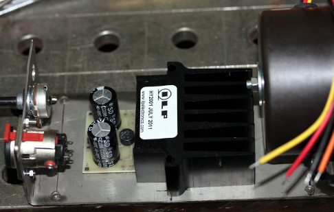
Sizes are identical though. We
still have to make up our mind with regard to the lights to build into this
robot. The yellow 1W LED light on the back side is mounted. There is place
for one more 12V light and eventualy a single 48V tungten filament light.
Some kind of handle is still left to be designed as well. Waiting for the
newly designed piggy pack board fot the ARM discovery and the AXO firmware...
Test assembly
of the complete robot. Mounting and soldering of the stabilized 12V power
supply for the lights. Seems we have to redesign the positioning of the 24V
power supply as the positioning as drawn in 2D is practically impossible:
either the wheel axis or the rim underneeth are in the way. Eiher we have
to find another way of mounting, or else redesign the entire power supply.The
power supply is now bolted on the chassis with two M6 bolts and nuts. It can
be taken out easily. Start wiring of all power supplies. Electric test, DC
voltages checked o.k. Wiring connectors to the midi-hub board. Note that the
board on the picture is not the one we will use in the final construction.
Sizes are identical though. We
still have to make up our mind with regard to the lights to build into this
robot. The yellow 1W LED light on the back side is mounted. There is place
for one more 12V light and eventualy a single 48V tungten filament light.
Some kind of handle is still left to be designed as well. Waiting for the
newly designed piggy pack board fot the ARM discovery and the AXO firmware...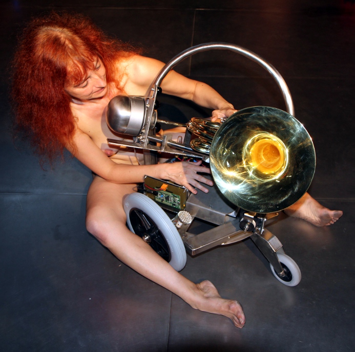
| (Terug) naar logos-projekten: | Terug naar Logos' index-pagina: | Naar Godfried-Willem Raes personal homepage... | Naar volledige katalogus instrumenten | |
Last update: 2023-10-11 by Godfried-Willem Raes
Technical drawings and data sheets:
Horn:
Arnolds & Sons, type AHR-301, serial number 121267. Arnold Stoelzel Gmbh, Postfach 5523, D-65045 Wiesbaden, Germany. Website: www.arnolds-sons.de
Mechanical parts & construction:
Ball bearings and flange holders in cast iron for the horizontal movement: INA RASEY20-N, LAG135030273 (from MEA)
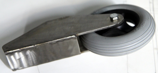
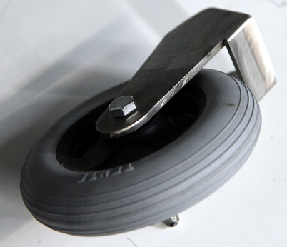
Wheels: Spoke wheels with polyurethane
tires: Large wheels Tente, 350 mm diameter, width 45mm, axis: 12mm. Small wheels:
Tente 125 mm diameter, width: 35mm, axis: 8mm..
All chassis parts made from
stainless steel AISI 316 or AISI 304
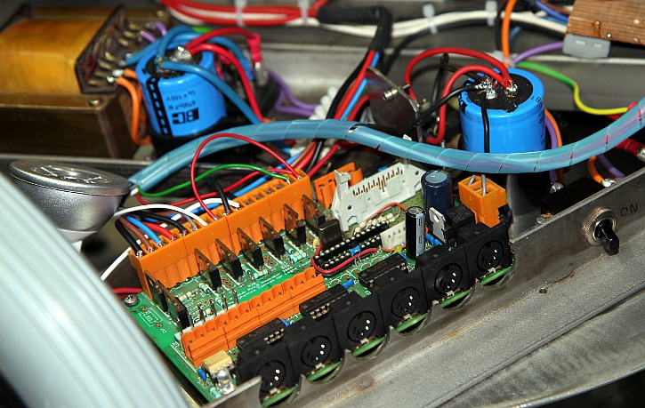
Electronic circuitry:
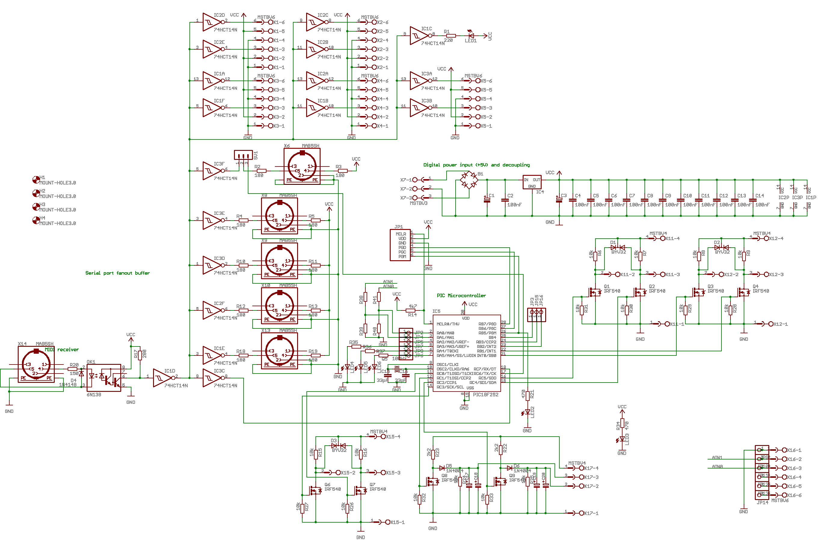
Overview:
Midi-hub board:
This board controls the three valves, the movement solenoids and three lights. It also hold the components for the +5V power supply.
Driver generator:
A development board for an ARM microprocessor is used here: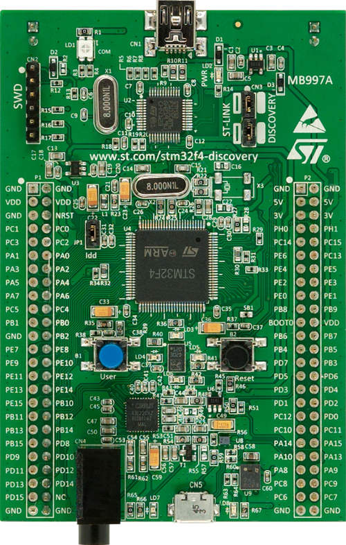 An STM32f4 discovery board.
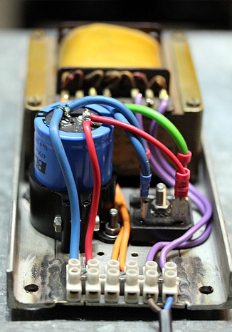
Power supply: This is the picture of the valve power supply module:
Compression driver unit: Model PADU 100, power rating 100W, impedance 16 Ohms. (Made in China) We have measured this component carefully and found the impedances in function of applied frequency as follows:11.4 Ohms @ 100Hz, 23.68 Ohms @ 1kHz, 26.7 Ohms @ 10kHz and 45 Ohms @ 25kHz. The acoustic load does influence the measured impedance at 1kHz over a 1:2 range: with the mouth completely closed it measures 32.8 Ohms and with the mouth completely opened but without any resonator, 15.35 Ohms. This phenomenon does not occur for the very low neither for the very high frequencies. The measurements were performed with our Hameg LCR meter, model HM8018. The frequency response is 100Hz to 10kHz. The thread for mounting is 1 3/8"-18 TPI. The 100W rated power of this driver must be understood as 'peak power', and thus in true rms terms would correspond to ca. 35Watt sine wave. Thus the maximum voltage that can be applied to the driver is 25V.
Solenoid valves:
Two different approaches were carried out. After evaluation, we decided to go for the second approach, using Laukhuff solenoids, as they operate much more silently than the tubular solenoid solution.
1.- Tubular solenoid assembly: (abandoned)
Solenoid type used for the valve pushers: Lucas Ledex (now distributed by Saia-Burgess) STA type 195207-228 (13.8 V DC @ 100% duty), 10 Watt, 7.8 N @ 5mm with 60 degree plungers. 26 mm diameter, height 52 mm. The required anchor displacement for the horn valves is 12 mm.
Note on the push tubular solenoids used to activate the rotary valves:
The following specs are valid at 20 degrees Celsius. Maximum holding force is 29 N
| 13.8V | 100% |
10 W |
17.78 mm in 41 ms |
2.54 mm @ 10 N |
| 19.6V |
50% |
20 W |
17.78 mm in 32 ms |
2.54 mm @ 18 N |
| 28.0V |
25% |
40 W |
17.78 mm in 22 ms |
2.54 mm @ 27 N |
| 44.0V |
10% |
100 W |
17.78 mm in 15 ms |
2.54 mm @ 40 N |
These solenoids may not deliver enough starting force to start the valve movement. Thus our design for pulse-hold solenoid drivers may be used here. This was the approach in <Bono>. This approach necessitates a bipolar power supply. The positive hold voltage can be reduced to 10 V, the negative velo-pulse voltage should be between 24 V and 36 V.
2.- August Laukhuff pull down magnet assembly : Type 300810, having a traject
of 10mm at a force of 10 Newton. (24V types have R=57 Ohm and draw 420mA current).
We made this assembly as it performs inherently more silent than the tubular
solenoid version. However the starting force is only marginally large enough
to activate the valves. Hence the circuit with the series bulbs working as voltage
dependent resistors from a 48V supply voltage.
3-- The horizontal movement makes use of a single large August Laukhuff bidirectional solenoid operated from 24V. The two windings have a DC resistance of 12 Ohms, hence the current drawn is 2A. Since we never activate both coils with the same power at the same time, a 2.5A power supply ought to be powerfull enough here.
Lights:
References: