Dr.Godfried-Willem RAES
Kursus Experimentele Muziek: Boekdeel 2: Live electronics
Hogeschool Gent : Departement Muziek & Drama
| <Terug naar inhoudstafel kursus> | naar player piano (inleiding) | Dit hoofdstuk is -vanwege de grote internationale belangstelling- niet beschikbaar in het nederlands. |
2116
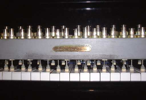
The Player Piano
In this chapter we will describe and discuss how to design and build a completely functional player piano...
The easiest way to use a Wintel computer to control striking mechanical objects (keys, bars, drums, cymbals, valves...) consists of using one a more I/O adresses , bringing these ports out after latching the data contents, and use the signals directly to drive bases or gates of power darlingtons or Mosfets which can switch the required solenoids on or off. If you want it to be midi controlled, Pavo offers a relatively cheap solution in the form of their midi computer kit with 64/128 output driver device. No way to use the midi velocity however along this track...
If the solenoids are powered from a supply with a voltage of ca. 2 to 5 times the nominal operating voltage of the coils, it becomes possible to controll the impact of the strokes through software: by carefully controlling the time (the width) of the pulse applied to the solenoid. Of course you have to guarantee that no coil ever stays under tension, since they are guaranteed to burn out under these circumstances. If the instrument required the anchors to stay in touch with the object, it is enough to apply a constant voltage, just a bit over the minimum holding voltage, to all solenoids.
Pulsewidth modulation offers another alternative possibility. But, when attempting to handle this through software only, you may quickly run into serious problems, particularly if the instruments you wanted to build, had to be polyphonic... Also, the solenoids when driven by PWM signals tend to get rather noisy...
Since in all struck instruments (pianos included) the volume is only dependent on the impact of the solenoid anchor on the object, it is enough to controll the energy supplied to the coils during the attack period.
Hardware approach:
In instruments such as the player piano, we had to derive this information from the velocity bytes in the note-on midi command, for each note individually. The data analysis of the midi stream was left to a dedicated microprocessor system. The controll however, still involves some electronic circuit bending. One of the very first working ideas we developped looked like this:
Note that this circuit has to be build once for every single object your instrument has to strike. So parts count will build up with the number of keys. This anyhow, if you want your instrument to have fast response and complete and true polyphonic possibilities.
The circuit around the 74F779 or 74HCT779 chip (a synchronous TTL counter) behaves as a digitally controllable monostable oscillator (a monoflop). A rising edge on the note on signal starts the counter and as long as pin 11 stays 0, new values appearing on the 7bit data input, are load into the count register. Counter data is latched into the register as soon an the signal on pin 11 goes high, so an external latch is not required. The counter is operated in count-down mode, starting from the value load on its input register. As soon as count 0 is reached, the TC (terminal count) output (pin 12) goes high. Hence also, the inverter following pin 12 of the 74779. The software has to guarantee that the note and velocity bytes are inverted in time, as compared to the order used in the midi protocol. First the velocity byte has to be send, only than the notebyte to which this information applies. Since the chip is synchronous, the user has to guarantee a clock pulse between the velocity data and the note-on command pulse. This could be realized through hardware as well, but we did'nt want to obscure the schematic too much. If you want to further develop this idea: it's quite simple, just insert a monoflop, triggered on the rising edge of the note hold signal. As to the counter used, a 74579 chip could be used as well, but pinning is different. The 74F579 comes in a 20 pin DIL package and has multiplexed I/O registers. The 74F269 can also be used, but occupies a large board space with its 24 pins and separate input and output ports. As I heard from some students, nowadays (2001) there seems to be increasing problems in getting these TTL components. So, before you start building this circuit, make sure you can get the required chips.
Note that the dynamic range can be tightly adjusted -controlled if you want, even by midi continuous controller commands- by adjusting the clock frequency. Exact settings depend highly on the types of solenoids used.
A similar approach is also possible using analog timer chips such as the infamous 555. In this case the velocity information should be converted to analog (an R2R network does just fine here) voltage fed into the control voltage input of the 555.
If you want optimum resolution , up to 16 bits (which is a lot better than even Boesendorf's player piano, using only 12 bit resolution...) , and highly flexible design, you could also opt for the classic 8253/8254 Intel timer chips. These chips contain 3 independent software programmable timers and can be easily configured for one-shot operation such as required for our purpose here. For a full 127 note controller you will need no less than 43 of these chips. If you have a choice, it will be almost mandatory to go for the C-Mos version (82C84).
A suitable circuit schematic for a board covering 12 notes or a full octave looks like this:
Circuit boards for this design are available from the author. Each board can accomodate all required components for a full octave (12 notes). The chip and semiconductor component list is:
The PC board for this circuit is depicted below:
We also designed PC boards covering two octaves. The problem with this design though, is that you need a A3 size printer to print the transparants for making the films. However, with this design you need only 4 boards for a piano and the wiring is greatly simplified. Here is the board:
The above board works best together with the specially designed demultiplexer board, working with a National Instruments DIO PCMCIA card. (see further)
Of course, the required software, although straightforward, ought to be worked out as well. Reading Intel's data sheet on the timer chip is essential. Support from within <GMT> is provided by the author, to simplify designs and further research. The schematic for a suitable demultiplexer to connect to your printer port is:
A suitable PC board (real size,but the gif file is 200% however) ) for the above multiplexer circuit used to steer these circuits from your printerport (or any other parallel port) looks like:
Note that using the printer port is impossible on NT machines or Windows 2000. To use the design on those operating systems, we use a National Instruments DIO PCMCIA card (PCI cards that are completely compatible are available as well). Since 2002, we have also implemented USB ports to work with our hardware. The schematic for the NiDAQ design is:
Of course, we also designed a printed circuit boards for this schematic. It works best in combination with the 2-octave boards shown above.
To give an idea about how to write code for this design, we give here a small excerpt from our <GMT> project:
Constant definitions:
Procedure for note ON:
SUB g_Note (BYVAL note AS BYTE, BYVAL velo AS BYTE) EXPORT
LOCAL retval AS LONG
LOCAL wvelo AS WORD ' 16 bit value
LOCAL cw AS BYTE
LOCAL param AS BYTE
IF ISFALSE velo THEN
       ppHold note, %False
       EXIT SUB
ELSE
       ppHold note, %True
END IF
wvelo = velo * 512 ' linear mapping, for test only - range 0.2ms to 65ms
PortOut %Preg,%VeloReg
PortOut %Padr, &B11 ' A0=1, A1=1 implies command writing to 82C54
Strobe %Preg,%Veloreg,0,%StrobeLength
PortOut %Preg,%NoteReg
cw = note MOD 3
SHIFT LEFT cw,6
BIT SET cw,5
BIT SET cw,4 ' 16 bit loading - lsb first! M0, M1, M2 = 0 for mode 0 counting, BCD= 0 for 16 bit binary counting, in microsecond units
PortOut %Padr, cw
Strobe %Preg,%NoteReg,0,%Strobelength
param = note \ 3
PortOut %Preg,%SelVeloPort
PortOut %Padr, param
Strobe %Preg,%SelVeloPort,0,%StrobeLength ' now we generate a strobe such that the 74154 selects the correct timer and latches the data
PortOut %Preg, %VeloOut ' send a strobe pulse
Strobe %Preg,%VeloOut,0,%StrobeLength ' now we should send 2 bytes of timer data (the velo information in 16 bits):
PortOut %Preg,%NoteReg
PortOut %Padr, LOBYT (wvelo)
Strobe %Preg,%NoteReg,0,%StrobeLength ' set A0,A1 to the correct timer:
Portout %Preg,%VeloReg ' we use this port to select the timer adresses via  A0,A1 = D0,D1
PortOut %Padr, note MOD 3 ' 0 = timer 0, 1=timer 2, 2= timer 3, 3= controll
Strobe %Preg,%VeloReg,0,%StrobeLength ' generate a strobe to latch this byte into the timer
Strobe %Preg,%SelVeloPort,0,%StrobeLength ' now once again for the MSB of the velo data:
PortOut %Preg,%NoteReg
PortOut %Padr, HIBYT (wvelo)
Strobe %Preg,%NoteReg,0,%StrobeLength
Strobe %Preg,%SelVeloPort,0,%StrobeLength ' now both lsb and msb have been sent to the timer. It should now be counting...
END SUB
For complete code examples in the context of a working program, look into out <GMT> source code. The appropriate procedures reside in the code module g_nih.dll or g_noh.dll. (Source code is in the module g_h.bas)
Of course criticism is possible on the rather large size of such a project. Unfortunately we could not retrieve information as to timer chips that would contain more than 3 timers... It's very hard to believe that the industry would not have a good use for timerchips containing at least 16, and why not 256..., independent timers... A similar remark is valid for the non availability of DAC chips with built-in sample and hold and more then 16 output channels...
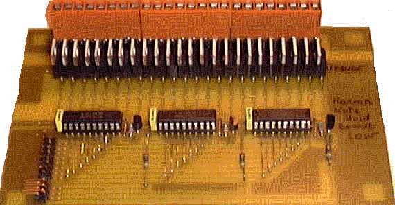
An assembled board covering a single octave looks like:
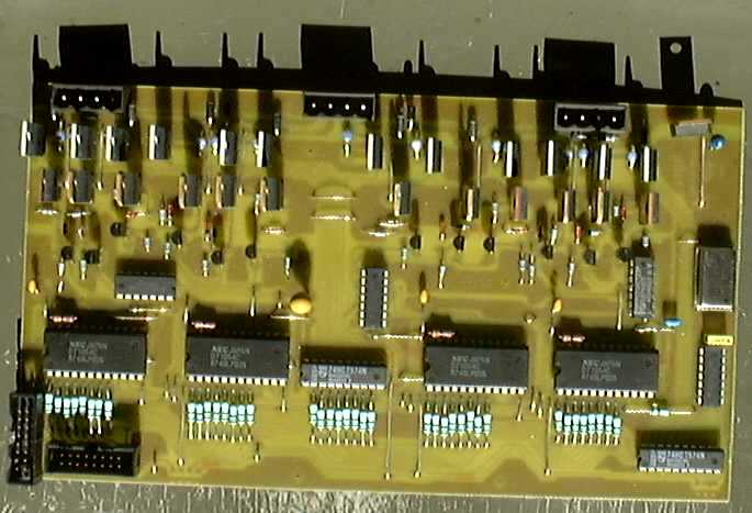 These
board can be purchased from the Logos Laboratories. Delivery time is ca. 4 weeks.
Fully assembled, a board costs 350Euros (price as of 22.09.2001). Two octave
boards are around 500 Euro. Enquire by .email
These
board can be purchased from the Logos Laboratories. Delivery time is ca. 4 weeks.
Fully assembled, a board costs 350Euros (price as of 22.09.2001). Two octave
boards are around 500 Euro. Enquire by .email
Solenoid hardware
For player pianos and similar keyboard instruments we advise the use of STA Series push tubular solenoids manufactured by Lucas Ledex in Vandalia, Ohio. The type number to order is 195207-2-28, for solenoids with following specs:
Simplistic approach:
In theory everyone should be capable of designing electromechanical and midi controlled instruments, using one of the nice kits Pavo sells. They should have a kit with a possibility to write the programm in the PROM yourself on a Wintel PC... at least that's what their add claims.
As to the kit for controlling up to 128 solenoids/relays from their catalogue, we have tried it and warn potential buyers for some inherent limitations of the design:
Multitasking approach:
An alternative to the hardware approach above, consists of using a multitasker to controll the individual solenoids. Here you have to set up a single task for each solenoid (so 88 for a player piano..., 128 tasks if you want a universal controller accepting all midi notes, or many more if you want to dig into the world of microtonal automated instruments...). Our <GMT> software (version > 4.18) can handle all this perfectly well. If you are not yet familiar with GMT, we refer you to chapter 1 of this course as well as to the relevant manuals on our website: http://www.logosfoundation.org/logos/gmt/gmt_intro.html
Each single key-task then controlls the ON time for the velocity pulse as well as the hold-pulse. The hardware becomes much simpler now and it is possible to just use the printer output port from a normal PC. You have to buffer the input. The schematic can be represented in block diagram as:
The above circuit sketch allows for up to 128 notes with 128 individual velocity controlls. The velocity controll can in this approach have virtually unlimited resolution. Of course you can save on chip count, by leaving out notes your application does not require. In any case you need two 8-bit latches for each group of 8 solenoids (and notes).
DETAILS:
A detailed -and tested- schematic for a demultiplexer boards looks like: (this circuit fits easily on a single Eurocard):
This board (just as the 8254 boards described before) can also be used with National Instruments DIO boards, if you use our adapter board to convert this output into something simular to standard printer ports. One of the reasons for going into NiDAQ devices having to with the fact that under Windows NT and Windows 2000 it is no longer possible to directly adres and use the ports of your PC. (Blame Bill Gates for this theft of property!). Software for both standard printer ports and NiDAQ devices is included in our GMT project.
Once you got this up and working, you can start building the note/velocity decoder boards. You need 1 board for each set of 2 octaves. So if we start from midi note 0,
the mapping is:
The circuit looks like:
So each board houses 6 74HCT574 latches. The inverters are 74HCT14, or anything similar. The outputs for the latches go to darlington and mosfet drivers as shown in our first schematic above. It is very well possible (and favorable for heat losses...) to substitute another power mosfet for the darlington, as shown in the schematic below:
With components -and voltages- shown, you can use any type of coil in as far as the current drawn does not exceed 2.5Amps, since that is the limit for the power mosfets. The coils we use are rated for continuous operation at 12 Volt. So, under no circumstances should you leave on the velocity voltage. In normal circumstances you do not need cooling for the mosfets. For the 2N3906 almost any fast small signal PNP transistor can be substituted. (Such as BC307, BC512, BC557, BC251, BC212, 2N3905...). The 2N3906 is rated at 40V / 200mA Ic. Power rating 0.35W, beta=100.
If you shop for mosfets, for the note-hold mosfet, make sure you use types that fully fire with gate voltages below 5Volts! The 4k7 resistors are not always required. They serve as protection for the mosfets in case the board gets disconnected and help discharging the gates faster during operation, thus limiting dissipation.
Possible alternatives for the note-hold mosfets are:
As to the velo-pulse mosfets, the situation is slightly different. In the schematic as shown, the pulse on the collector of the PNP transistor, connected to the mosfet gate, ranges from -Vcc to +5V. If you do not fit a zener diode, you have to select a power mosfet capable of withstanding a Vg of this amplitude. The IRF540, 610 etc. series can withstand 20V on their gates, so if you use this type, -Vc should not exceed -15V. If you consider using the RFP... types, notes that without extra protection, the -Vc voltage should not be larger than -5V. It will be clear that this would compromise the controll range for the velocity pulses. By fitting a zener diode between the gate and -Vc of the mosfet, you can limit the gate voltage to a safe value for the mosfet you select.
For all our applications we have never used cooling on the Mosfets. You can calculate dissipation easily as follows:
You should try to limit this value to below 2Watts.
Since the switching speeds in this application are very low, we can safely neglect the dissipation caused by charging/discharging the gates.
Under no circumstances should you forget the surge protecting diodes over the solenoids. Any reasonably fast 1Amp 200V diode will do. Note that you need as many driver circuits as you have notes on the instrument you want to automate.
The software was implemented under <GMT>, and is available (if not found on this website) on request. Note that since this player piano inherently does not use midi (although the software allows users to just control the piano (or other automated instrument) via midi command), we are not limited to the slow speed so typical for midi! So, here -provided our power supply is powerfull enough-, we can indeed play 88-note clusters. without making them sound as arpeggios.
To make the software a mirror of the hardware implementation, we created a specific prototype for our code, wherein each element contains the exact bit contents of each latch:
TYPE Akeys BYTE ' makes a single 128-bit variable, if adressed by its pointer.
b000007 AS BYTE ' contents of latch 1
b008015 AS BYTE ' contents of latch 2
b016023 AS BYTE ' contents of latch 3
b024031 AS BYTE ' contents of latch 4
b032039 AS BYTE ' contents of latch 5
b040047 AS BYTE ' contents of latch 6
b048055 AS BYTE ' contents of latch 7
b056063 AS BYTE ' contents of latch 8
b064071 AS BYTE ' contents of latch 9
b072079 AS BYTE ' contents of latch 10
b080087 AS BYTE ' contents of latch 11
b088095 AS BYTE ' contents of latch 12
b096103 AS BYTE ' contents of latch 13
b104111 AS BYTE ' contents of latch 14
b112119 AS BYTE ' contents of latch 15
b120127 AS BYTE ' contents of latch 16
END TYPE
In the code we use two global variables Vkey and Nkey, standing for the contents of the velocity latches and note-latches respectively.
There are different approaches possible. First we can define individual tasks within GMT, one for each key:
1.- Individual key-task implementation:
The task-code written in PowerBasic - we give here the code snippet for midi-keys 0 and 1- to run in <GMT> looks like:
END IF
IF ISFALSE Task(%Toets0+ note).tog THEN
END IF
ppVelo note, %False ' velo bit off
ppHold note, %True ' hold ON
StopTask %Toets0 + note ' note stays on until
task is switched on again, with level set to zero.
2.- In a second approach, we do not have to use tasks at all, but we take profit of the multimedia timers integrated in the Win32api. These timers are interrupt based. They make use of callback functions that we have integrated into our DLL library. However, in this approach we are limited to the timing resolution of the PC used and to the amount of simultaneous timers windows supports.
The code to make our player piano listen to midi-input (we have one such task for each midi channel, the channel can be selected by the user from the command cockpit in GMT) simply looks like:
To see the latest complete source, cfr: http://www.logosfoundation.org/logos/gmt/gmt_pp.inc . Note that the low level driver code resides in gmt_lib.dll, thus hiding musicians for error prone coding that could possibly damage the hardware.
Better even, download the complete GMT in zipped form: http://www.logosfoundation.org/logos/gmt/gmt_source.zip
If the interest in this building project is high enough, we consider offering PC-boards for all above circuitry. Contact the author by email: godfriedwillem.raes@logosfoundation.org
A design for the parallel port demultiplexer looks like this:
If you want to etch it, this artwork has to be placed in contact with the photosensitive layer of the PC board.
The PC-boards containing 2 octaves of note drivers may look like:
The last board you will need, is for the velocity drivers. Again , the following artwork is a single eurocard board covering 2 octaves:
If you want to make your own PC boards, then you can print this artwork with a laser printer on tranparancies as used for overhead projectors. These films can be used to expose the photosensitive PC boards directly.
We made a quick picture of one of these note-hold boards:
Notes:
1.- as off 01.02.2000: PC boards as well as complete kits for the above project are available from the author. Pricing information can be obtained by email: godfriedwillem.raes@logosfoundation.org
Prices for note and velo board depend on the solenoids you want to use (current and voltage) as well as on whether you want darlingtons or mosfets.
We also designed compatible boards to controll heavy duty stepping motors, since we needed these in our automated rototom instrument. (cfr. Rotomoton).
2.- The note-hold boards described here can also be used with PAVO's midi kits. These kits do not support velocity information handling however. The advantage is only that no PC is required to controll your automated instrument.
The circuit we designed -to be connected to the DIL header labeled J5, expand conn. provided on PAVO's controller board, looks like:
PC boards for this circuit are available also from the author. If you want to do the etching yourself, here is a suitable PC board layout:
IMPORTANT NOTICE:
Copyright & Patents strictly prohibited. We herewith put both code and hardware design in the public domain and whoever patents or copyrights any of our inventions -thereby blocking scientific and artistic progress- , or the outcomes thereof in any country, will be prosecuted. These design can be freely used on the only condition that their author be mentioned.
Godfried-Willem Raes
The newest designs are documented via this link
Filedate: 2009-03-02
| Terug naar inhoudstafel kursus: <Index Kursus> | Naar homepage dr.Godfried-Willem RAES | Deze pagina is niet beschikbaar in het nederlands |