An old recipe for a stabilized power supply without using semiconductors nor vacuum tubes: the saturated core transformer.
Long before vacuum tubes, let alone semiconductors, came to join the world of electric design, it was already possible to design and build regulated power supplies. Quite a few techniques were used:
- - stabilization by using the voltage dependent resistance characteristics of tungsten filament lamps. The lamps are connected in parallel with the load. This technique for voltage stabilization can be found in very many designs of sine wave generators as well (Hewlett Packert, for instance).
- - motorized regulation using a variac or a rheostat, pretty similar to the Watts-regulator as used in steam engines. Such designs mostly apply to very high power supplies from 500 W on.
- - stabilization by using current controlled inductors (magnetic amplifiers).
The device required to achieve this last option is a saturated core transformer. Such a transformer has three windings, often wound on three separate legs of a closed E-core. The main winding is switched in series with the regular power supply transformer and it is the inductance of this winding that will be modulated by the current taken from the power supply.
If you look at the circuit drawing above -the saturated core transformer is labeled Tr1- you should notice that the two secondary windings are connected in series but out of phase. Thus no AC voltage will be generated over these windings, provided those windings are closely identical. The DC current through the load runs through this winding. As the inductance of the transformers primary goes down as the saturation is approached, the impedance of the coil will go down as well, and as this coil is in series with the power supply transformer, this one will get a higher voltage. Thus the power supply will regulate load variations by modifying the primary voltage of the main transformer. Here is a picture of such a transformer:
Note also that the core ought to be underdimensioned in comparison to a normal transformer, to guarantee saturation to occur.
Power supplies build along this principle tend to turn out very bulky. However, they have an inherent sturdiness and as long as their current rating is not exceeded for a long time (the fuse is an essential component...) they have eternal life and require no maintenance.
We never encountered such circuits in high voltage power supplies for vacuum tube circuits -probably because the current these tend to draw is relatively low- but at the other end, very often in power supplies serving telephone exchange equipment. These power supplies offer voltages in the range 24 to 48V at current rating between 2 and 10 A. One day, we took such a circuit (it must date from the period between 1935 and 1950) apart and reverse engineered it completely. We got it from the equipment that was to be disposed off at the move of the former IPEM studio in Ghent, from its premisses at Muinkkaai to the much smaller university rooms at Rozier. It was used in that studio as a power supply for one of the sound generators they had in use in the sixtees. The keyboard part of that generator is now in the collection of the MIM in Brussels, as we donated it to them. Here is the reconstructed circuit drawing of that power supply:
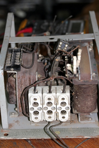
And, here are some pictures of the power supply before cleaning up: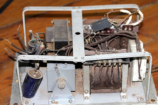
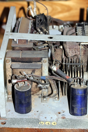
We measured the wire gage on the saturation transformer Tr1 secondaries as 1 mm diameter. The DC resistance of both windings in series equals 0.8 Ohm. If we assume a current density in the copper wire of 3 A/mm2, this would indicate a current rating of 2.5 A. This seems consistent with the size and weight of the transformers, indicating a power between 65VA and 100VA. None of the output terminals are grounded, thus the voltage is floating versus the chassis. There is no mains grounding provision neither, but presumably the entire unit was built into a steel cabinet that itself was connected to mains ground. Note that the device still works today! If we would change anything, it would be the leaky selenium rectifier by replacing it with a silicon type, and the two electrolytic capacitors. We would at the same time increase their value to at least 10mF, thus improving the ripple reduction achieved with the Pi low pass filter using a choke considerably. Capacitors with such high values were simply not available at the time this supply was designed and build. By selecting one of the ten taps provided on Tr2's secondary, the voltage can be set to voltages in the range 25 to 35V. The mains voltage can be 220, 190, 130 or 110Volts. All measurement data come from us, as no documentation could be traced.
Power supplies following this principle can also be found in electronic music equipment in use up to the mid sixties of the 20th century. Examples are electronic organs (Hammond and derived designs), electromechanical sequencing equipment, tape delays and old Springer-machines (used for changing pitch without changing duration with analog tape recordings) with rotating heads and such more. We also encountered such power supplies in pipe organs using electric valves in the windchest. Here is an exemple:
If it comes to restoration, our advice would be not to replace them if they still work properly. If a repair is practically unfeasible, it should be replaced with an alternative pure analog and linear design. Stay away from SMPS type power supplies as these will introduce a lot of high frequency noise in the audio circuitry driven by them. Moreover, if they were used in the original piece of equipment, to drive inductive components of any kind, only linear alternatives are possible as SMPS power supplies rarely function well in circumstance where they have to feed fast switching heavy inductive loads. In fact the saturated core power supply is still the most sturdy design if it comes to regulated power supplies for inductive loads such as solenoids and stepping motors.
For this reason, in part also as an experiment, we used one of the spare saturated core transformers we had in stock (type number AD36255) , to construct a new power supply using otherwize modern components in 2015. The circuit diagram follows closely the original design:
Ripple on the output is <10mV with a 1A load. The AC voltage over the primary of the saturated core transformer varies between 30 and 105V, depending on the load. The measured regulation results are -for nowadays standards- far from ideal:
This curve was obtained with a 50 Ohm / 200W variable rheostat as a load. A noticable mechanical hum -proportional to load current- was noticed from the saturated core transformer. This hum is clearly not caused by our chassis, as we made it from stainless steel. Only impregnation of the windings with epoxy rosin could improve this. It will be clear that regulation gets better as the current is increased. For the components used here, the maximum output current should be limited to 5.7 A. The 2.5 k wire wound resistor on the output serves as a 'preload' limiting the open voltage output to 48V as well as for decharging the capacitors when the power supply is switched off. An incandescent bulb of a suitable value at this place could further improve regulation. The curve drawn in orange gives the DC voltage measured over the saturation winding of the transformer. DC resistance of this winding equals 0.8 Ohm. As predicted by Ohm's law, this is nearly a straight line. The slightly downward curve near the right is caused by the increasing resistance of the coil as it starts warming up.
dr.Godfried-Willem Raes
Bibliographic references:
GILLON, Dr.Ir.E, "Elektrotechniek", deel 2 'Elektrische Machines' ed. Standaard Uitgeverij Scriptoria, Antwerpen / Utrecht, 1969 (8e uitgave). Magnetische versterkers worden hierin behandeld: p.149 - 154.
This article is part of a research project on Experimental Legacy financed in part by the Orpheus Institute in Ghent.
First version: december 12th 2014Last updated: januar 2025
www.orpheusinstituut.be
to home page Godfried-Willem Raes